If you’ve ever wondered whether aligner thickness really matters — spoiler alert: it does! A recent study in the Korean Journal of Orthodontics (2025) by Wang et al. dives deep (literally, histologically deep) into how the thickness of clear aligners affects tooth movement and the surrounding periodontal tissues.
🧪 The Setup
Researchers used New Zealand rabbits fitted with aligners of two different thicknesses — 0.38 mm and 0.68 mm. Using 3D scanning, micro-CT, and histological analysis, they explored how each aligner influenced:
Tooth movement speed
Root resorption
Periodontal ligament (PDL) changes
Inflammatory and bone-remodeling markers
⚙️ The Science in Motion
The thicker aligners (0.68 mm) delivered stronger forces, causing more PDL deformation, larger resorption craters, and higher inflammatory marker expression (IL-6, IL-1β).
The thinner aligners (0.38 mm) produced gentler forces, enabling slightly faster tooth movement with less inflammation and more balanced bone remodeling (more osteoclasts on the compression side, stable ALP and OPN expression).
🧠 Mnemonic — “THIN” aligners are KIND:
T — Tiny force, tissue-friendly
H — Higher biological harmony
I — Inflammation less
N — Natural remodeling prevails
Category
Parameter
0.38 mm Aligner (Thinner)
0.68 mm Aligner (Thicker)
1. Mechanical Characteristics
Initial Force → Steady Force
~0.88 N → 0.45 N
~1.58 N → 0.80 N
Force Profile
Lower, more physiologic
Higher, more stressful
Tooth Movement Speed
Slightly faster (efficient force decay)
Slower (higher sustained force)
2. Periodontal Ligament (PDL) Response
PDL Deformation
Minimal, controlled
Pronounced, compressive
PDL Stress Distribution
Even and well-distributed
Concentrated, deeper compression
3. Root Integrity
Root Resorption Pattern
Small, shallow craters
Larger, deeper craters
4. Cellular Response
Osteoclast Distribution
Surface-based, well-organized
Deeper, scattered, disorganized
Osteoblast/Osteogenic Activity (ALP, OPN)
Higher early osteoblastic activation → rapid bone formation
Delayed osteogenic response
5. Molecular Response: Inflammatory Markers
IL-6
Low
High
IL-1β
Lower expression
High expression
Overall Inflammatory Load
Controlled
Amplified
6. Molecular Response: Bone Remodeling Markers
TRAP (qRT-PCR)
Controlled, efficient osteoclastogenesis
Elevated but disorganized
RANKL Expression
Balanced → supports controlled resorption
Elevated → promotes excessive resorption
VEGF Expression
Balanced angiogenesis, stable remodeling
Increased angiogenesis due to stress
7. Compression- and Tension-Side Biology
Tension Side
↑ OPN, ↑ ALP → early osteoblast differentiation
Low osteogenic activity
Compression Side
Controlled inflammatory markers
High IL-6 → heavy inflammatory burden
8. Overall Biological Pattern
Remodeling Outcome
Harmonious, biologically efficient tooth movement
Stress-driven remodeling with higher risk of adverse effects
Clinical Interpretation
Safe, physiologic forces → predictable movement
Higher forces → slower movement, more inflammation, increased resorption risk
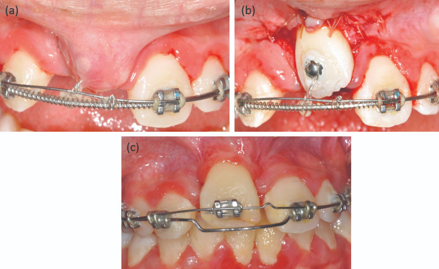
When orthodontists treat unerupted or impacted teeth (especially in the anterior region), several complications can occur:
Tooth devitalization (loss of vitality)
Re-exposure or uncovering after surgery
Ankylosis (tooth fused to bone)
External root resorption
Damage to adjacent teeth
Marginal bone loss
Gingival (gum) recession
➡️ These complications can prolong treatment, cause esthetic problems, and even lead to tooth loss.
Why These Problems Happen
Historically, clinicians focused on surgically exposing the tooth (“uncovering”) to bring it into the arch. However, the soft tissue (gingiva) around the tooth was often not given enough attention.
Most early surgical techniques, such as “simple complete exposure,” focused only on getting to the tooth, without considering:
What kind of mucosa (attached gingiva vs. alveolar mucosa) covered it
How that tissue would behave once orthodontic movement began
Why Soft Tissue Type Matters
There are two main kinds of oral mucosa:
Attached gingiva (masticatory mucosa):
Firm, tightly bound to bone
Designed to resist mechanical stress and prevent muscle pull on the gum margin
Ideal marginal tissue around a tooth
Alveolar mucosa:
Movable, thin, and elastic
Poor at resisting muscle pull or inflammation
Not suitable as a marginal tissue
If a tooth is uncovered and surrounded only by alveolar mucosa, the tissue tends to get inflamed easily, which can lead to bone loss and gingival recession as the tooth is moved orthodontically.
What the Ideal Surgical Approach Should Do
Instead of just exposing the tooth, the surgical goal should be to:
Ensure that a band of attached gingiva surrounds the crown once the tooth is exposed.
Create a healthy, functional marginal tissue environment before starting tooth movement.
This provides several key advantages:
Prevents the need for repeated dressings or barriers to keep the tooth exposed
Allows faster and smoother tooth movement (no soft-tissue obstruction)
Prevents gingival recession and bone loss during orthodontic traction
Why Inflammation Is a Risk Factor
Periodontal experience shows that tooth movement in the presence of inflammation is risky — it can accelerate bone loss. Since alveolar mucosa is prone to inflammation, it’s unsafe to move a tooth unless it’s surrounded by healthy attached gingiva.
Thus, the uncovering procedure must integrate periodontal principles — ensuring that the final gingival condition supports tooth health and stability.
ORTHODONTIC CONSIDERATIONS BEFORE SURGERY
Why create space before uncovering the tooth?
There are two main reasons:
For eruption and alignment:
If adequate space isn’t available in the arch, the unerupted tooth has no place to move into.
So, before any surgical exposure, orthodontic space creation ensures there’s enough room for the tooth to erupt or be moved into proper alignment.
For surgical soft-tissue management:
The edentulous (toothless) space left in the arch is covered by attached gingiva, which can be used as a donor site.
This tissue can then be repositioned apically or laterally as a partial-thickness flap to cover the exposed tooth crown after surgery — ensuring the presence of healthy, attached gingiva around the tooth.
SURGICAL PROCEDURE: STEP-BY-STEP LOGIC
Anesthesia and incision:
Local infiltration anesthesia is administered.
The surgeon makes an incision along the ridge in the edentulous area — where the impacted tooth lies beneath.
Determining incision design:
The height (incisogingival dimension) of the incision depends on how much attached gingiva is present on the adjacent teeth or its opposite tooth (antimere).
If there’s plenty of attached gingiva nearby, a larger flap can be created and repositioned.
Flap elevation and bone removal:
Vertical releasing incisions are made to free the attached gingiva.
Connective tissue over the unerupted tooth is gently removed.
Bone is removed only up to the height of contour of the crown, not beyond the cementoenamel junction (CEJ).
⚠️ Why stop at the CEJ? Because this is the zone where the dentogingival attachment (junctional epithelium + connective tissue attachment) naturally forms. If bone is removed beyond the CEJ, it can disrupt this zone and increase the risk of gingival recession — something confirmed in animal (monkey) studies.
PLACEMENT OF ATTACHED GINGIVA (THE GRAFT STEP)
Where and why to place it:
The graft (attached gingiva) is positioned to cover:
The CEJ, and
About 2–3 mm of the crown.
This positioning serves three biologic and mechanical purposes:
Establishing stable attachment:
It helps form a healthy supra-alveolar connective tissue attachment between the tooth root (cementum) and alveolar bone.
This ensures periodontal stability and prevents bone loss.
This seal prevents bacterial ingress and inflammation — something alveolar mucosa cannot achieve.
Allowing safe tooth movement:
As the tooth is orthodontically pulled into the arch, tension develops in the gingiva.
If the gingiva is attached higher (more coronally), it can accommodate slight apical repositioning during movement without losing its protective role.
In simpler terms — the gum margin “moves with the tooth” instead of receding.
POST-SURGICAL STEPS
Sutures are placed on both sides (mesial and distal) to hold the graft stable over the tooth.
A periodontal dressing is placed for 7–10 days to protect the surgical site and allow:
Reattachment of the tissue to the tooth
Epithelial healing over the area
Once the dressing is removed:
A bonded orthodontic bracket is attached directly to the tooth.
Light orthodontic forces are applied immediately to begin eruption or alignment.
🔑 Light force is critical — it allows physiologic movement without jeopardizing the new soft tissue attachment.
Why This Method Works Better
The described surgical exposure technique (with attached gingiva placement) is particularly advantageous for teeth with delayed or retarded eruption. It provides both biologic and mechanical benefits that improve eruption success and tissue health.
What Actually Delays Eruption: Bone or Soft Tissue?
Traditionally, it was thought that bone acts as the main physical barrier delaying eruption.
However, clinical and biologic observations show that this is not true unless the tooth is ankylosed (fused to bone).
👉 The rate of bone remodeling (turnover) is actually faster than the rate of remodeling in the overlying soft tissue.
➡️ Therefore, the soft tissue — not the bone — is often the main factor that slows eruption or impedes tooth movement.
Managing Long-Distance Tooth Movement
When a tooth has to travel a large distance to reach the arch:
The surrounding gingiva may begin to “bunch up” as the tooth moves.
In such cases, minor excision of excess tissue may be required to achieve:
Ideal gingival contour,
Correct tooth positioning,
Long-term posttreatment stability.
The key to managing delayed eruption lies not in removing more bone but in controlling and reconstructing the soft tissue environment. Creating a zone of attached gingiva around the uncovered tooth transforms the biologic response, allowing stable eruption and long-term periodontal integrity.
📍 The Challenge: Making Open Bite Correction Stay That Way
If you’ve ever treated (or even just planned) a patient with an anterior open bite, you know the struggle is real. The correction is dramatic, but so is the potential relapse. That’s why one of the classic questions in orthognathic literature is:
“How stable are Le Fort I intrusion osteotomies — and what happens when we combine them with mandibular surgery?”
A landmark paper by Hoppenreijs et al. (1997, Int. J. Oral Maxillofac. Surg. 26:161–175) tackled exactly this, and it remains one of the most cited long-term studies on skeletal and dento-alveolar stability.
Study Design
Retrospective 3-centre study (Nijmegen, Arnhem, Amsterdam)
267 patients (210F, 57M) with anterior open bite (Class I / II)
Mean age: 23.6 years
Mean follow-up: 69 months (20–210 months)
Procedures Evaluated
Procedure
n
Fixation
Additional surgery
Le Fort I (1-piece)
77
Wire / Rigid
± Genioplasty
Le Fort I (segmented)
67
Wire / Rigid
± Genioplasty
Le Fort I + BSSO
98
Wire / Rigid
± Genioplasty
Total
267
153 wire, 114 rigid
136 with genioplasty
Key Findings
1. Overall Stability
Both Le Fort I and bimaxillary osteotomies showed good skeletal maxillary stability.
Rigid fixation provided superior stability for both maxilla and mandible compared to wire fixation.
Mean final overbite: +1.24 mm
Residual open bite: 19% (no vertical incisal overlap at long-term follow-up)
2. Le Fort I Osteotomy Alone
Vertical and horizontal stability: Excellent when rigid fixation used.
Wire fixation: Showed slight superior movement during IMF (4–6 weeks) followed by mild downward relapse later.
Maxillary downward movement: ~0.28 mm anteriorly, ~0.52 mm posteriorly over entire follow-up.
Dentoalveolar changes: Minimal but present; posterior tooth extrusion contributed to late relapse.
3. Bimaxillary Osteotomy (Le Fort I + BSSO)
Initial stability: Comparable to Le Fort I alone.
Late vertical changes: Slightly greater downward movement and posterior rotation of maxillomandibular complex due to molar extrusion.
Mandibular relapse tendency: Mild clockwise rotation and posterior movement observed, especially in wire fixation cases.
Rigid fixation: Reduced mandibular relapse significantly during early postoperative phase.
4. Effect of Fixation Method
Fixation Type
Maxillary Stability
Mandibular Stability
Long-Term Relapse
Rigid fixation
Best vertical & horizontal control
Excellent early stability
Minimal (<1 mm)
Wire fixation
Good initial, but mild late downward drift
Clockwise rotation tendency
Greater overjet relapse
Rigid fixation minimized both vertical relapse and mandibular rotation, providing superior long-term occlusal stability.
5. Segmentation of Maxilla
One-piece vs. multi-segment Le Fort I showed no significant differences in overall skeletal stability.
Minor trends:
Multi-segment group → Slightly less early relapse of overbite
One-piece group → Greater posterior molar extrusion in long term
Conclusion: Segmentation can improve arch coordination but does not compromise skeletal stability.
Overbite relapse not significantly different between procedures due to compensatory dental changes.
Factor
Effect on Stability
Fixation type
Rigid > Wire (esp. in long-term)
Segmentation
Minor effect; slightly better overbite stability early post-op
Orthodontic treatment / Genioplasty
No significant effect
Le Fort I vs. Bimaxillary
Comparable maxillary stability; bimaxillary had slightly more dental relapse
Institution / Surgeon variation
No significant impact after statistical correction
At-a-Glance Summary
Parameter
Observation
Implication
Maxillary relapse
<1 mm vertical, 0.18° horizontal
Clinically minimal
Mandibular relapse
Slight clockwise rotation in wire group
Use rigid fixation
Overbite at 6 yrs
+1.24 mm
Acceptable stability
Open bite recurrence
19%
Mostly dental, not skeletal
Rigid fixation
↑ Stability (maxilla + mandible)
Preferred protocol
Q1.
A 23-year-old female with a Class II skeletal pattern and anterior open bite undergoes a Le Fort I intrusion osteotomy with bilateral sagittal split advancement (BSSO). Six months later, you notice mild clockwise rotation of the mandible and a 1 mm increase in overjet. Which of the following is the most likely cause of this relapse pattern?
A. Incomplete mandibular advancement during surgery B. Posterior molar extrusion due to dento-alveolar adaptation C. Condylar resorption after fixation D. Maxillary segmental instability E. Excessive postoperative orthodontic intrusion of anterior teeth
✅ Correct Answer:B. Posterior molar extrusion due to dento-alveolar adaptation Explanation: Hoppenreijs et al. observed that most long-term vertical relapse in anterior open bite cases was dento-alveolar, not skeletal. Posterior molar extrusion leads to downward–backward rotation of the mandible and mild relapse in overjet/overbite.
Q2.
A 25-year-old male undergoes a Le Fort I intrusion osteotomy stabilized with intraosseous wire fixation. At 3 months post-op, cephalometric analysis shows further superior migration of the maxilla compared to the immediate postoperative position. What is the most plausible explanation for this unexpected superior movement?
A. Sutural remodeling after intrusion B. Tightening and remodeling of suspension wires during IMF C. Loss of vertical dimension due to occlusal settling D. Postoperative condylar compression E. Reduction in nasal septal resistance
✅ Correct Answer:B. Tightening and remodeling of suspension wires during IMF Explanation: Hoppenreijs et al. found that patients with wire fixation often exhibited continued superior migration of the maxilladuring IMF. This was attributed to wire tension and bony remodeling, not relapse.
Q3.
You are planning a Le Fort I osteotomy for a 21-year-old patient with anterior open bite and posterior dento-alveolar hyperplasia. The case requires segmentation to correct arch form discrepancies. Based on evidence from Hoppenreijs et al., what is the anticipated effect of segmentation on long-term skeletal stability?
A. Significantly reduces stability of the maxilla B. Increases relapse risk due to multiple osteotomy sites C. Comparable stability to one-piece osteotomy D. Leads to more posterior rotation of the maxilla E. Requires rigid fixation to maintain stability
✅ Correct Answer:C. Comparable stability to one-piece osteotomy Explanation: Segmented Le Fort I osteotomies showed no significant difference in long-term skeletal stability compared to one-piece procedures. Minor trends included slightly better early overbite control and more posterior molar extrusion over time.
Q4.
A 24-year-old female underwent a Le Fort I + BSSO procedure with rigid fixation. At 1-year follow-up, cephalometric data show <1 mm maxillary vertical change and stable mandibular position. Which statement best explains this stability outcome?
A. Rigid fixation neutralizes early skeletal remodeling and dental compensation B. Rigid fixation prevents posterior rotation by controlling condylar movement C. Rigid fixation minimizes both skeletal and dento-alveolar relapse tendencies D. Rigid fixation enhances post-surgical eruption of molars to stabilize occlusion E. Rigid fixation alters growth pattern of the anterior cranial base
✅ Correct Answer:C. Rigid fixation minimizes both skeletal and dento-alveolar relapse tendencies Explanation: Rigid internal fixation offers superior control of both vertical and horizontal stability in the maxilla and mandible. It significantly reduces relapse compared to wire fixation, as confirmed in Hoppenreijs’ study.
Q5.
A 26-year-old female treated with Le Fort I intrusion osteotomy presents with a 2 mm open bite recurrence five years later. Radiographs show stable skeletal landmarks but slight molar extrusion. How would you classify this relapse according to Hoppenreijs et al.?
A. Skeletal relapse due to vertical maxillary instability B. Dento-alveolar relapse due to posterior dental extrusion C. Surgical relapse due to fixation failure D. Compensatory mandibular resorption E. Combined skeletal-dental relapse
✅ Correct Answer:B. Dento-alveolar relapse due to posterior dental extrusion Explanation: Hoppenreijs et al. emphasized that most relapse in open bite correction is dento-alveolar, not skeletal. Posterior molar extrusion results in mild mandibular clockwise rotation and open bite recurrence without significant skeletal displacement.
Q6.
You’re comparing outcomes between two patients:
Patient A: Le Fort I osteotomy + wire fixation
Patient B: Le Fort I osteotomy + rigid fixation
At long-term follow-up, Patient A shows 0.5 mm more downward maxillary drift and mild overjet relapse. Which clinical decision could have prevented this difference?
A. Use of IMF for longer duration B. Inclusion of genioplasty C. Use of rigid internal fixation during osteosynthesis D. Multi-segment instead of single-piece Le Fort I E. Additional intermaxillary elastics post-surgery
✅ Correct Answer:C. Use of rigid internal fixation during osteosynthesis Explanation: Rigid fixation (plates/screws) offers superior vertical and horizontal control, reducing both skeletal and dental relapse. Wire fixation, though historically common, allows more downward drift and mandibular clockwise rotationpostoperatively.
1. How did your journey in the dental profession begin, and what were the milestones that shaped it?
From the very beginning, I knew I didn’t just want to be a dentist — I wanted to be a holistic dentist. For me, that meant stepping into every kind of setup possible. I’ve worked in super glam, high-end clinics where patient detailing and experience matter the most, in fast-paced corporate chains where efficiency and systems rule, and in CGHS/government setups where limited resources challenge your creativity and compassion.
Each of these experiences shaped me in unique ways — teaching me empathy, precision, and adaptability — lessons I carry into my practice every single day.
2. What inspires you to stay passionate and committed to dentistry, even during challenging times?
People inspire me. Over the years, I’ve noticed a beautiful shift — patients today are genuinely curious about their smiles. They ask questions, they care about their oral health, and they’re invested in improving it. Seeing how a small change — sometimes as simple as aligning a tooth or improving a shade — can completely transform someone’s confidence is what keeps me going. And of course, dentistry allows me to be my own boss — a privilege that pushes me to stay committed and creative, even during tough days.
3. Who is your role model in dentistry, and how have they influenced your professional journey?
My biggest inspiration is Dr. Shruti from MAIDS. She’s done both her BDS and MDS there, and what amazes me most is her discipline. Even today — while managing family life and raising two kids — she studies for a few hours every single day. That level of dedication reminds me that dentistry isn’t a career you complete; it’s a lifelong learning journey. I aspire to bring that same philosophy to my practice — to always stay updated so my patients receive care that’s rooted in both compassion and the latest science.
4. How do you balance academics, work, and personal interests?
For me, balance isn’t optional — it’s essential. Dentistry can be intense, so I make sure to pause and recharge when needed. I’ve even taken two-month breaks between jobs just to travel, rest, and reset before starting fresh. Some people might think that’s unconventional, but that balance fuels my best work. When you’re happy and fulfilled outside the clinic, you naturally become a more patient, empathetic, and focused dentist inside it.
5. What advice would you give to dental students and young professionals?
The early stages can be tough — there’s little earning, lots of expenses, and often a sense of uncertainty. But don’t let that phase define you. Use that time to learn, document, and grow. Keep updating your skills and build expertise in areas your peers might overlook. When you do that, you create your own niche — and patients will value that uniqueness. Remember, confidence comes from competence. Keep learning, and everything else will follow.
💎 A Smile That Reflects a Life Well-Lived
Dr Himani Hasaji’s story is more than a professional journey — it’s a lesson in purpose, balance, and evolution. She’s not just crafting smiles; she’s crafting a philosophy that blends science, art, and humanity.
From wax carvings to real-life artistry — Dr Janhavi Bangar’s journey through dentistry is a story of growth, grit, and genuine passion. In this candid interview, she opens up about the milestones that shaped her, the mentors who molded her mindset, and the balance between precision and play in her life as a young dentist.
Beginnings: Finding Meaning in Every Milestone
1️⃣ Can you share how your path in the dental profession began and the key milestones that shaped it?
Honestly, my path started a bit like a wax carving — rough at the edges but shaping into something meaningful. One of my earliest “wow” moments was assisting in an implant surgery. I remember thinking, “We literally put screws into bone and call it art — this is wild and fascinating!” Another turning point was getting 73% in my first year. It wasn’t just a grade; it was proof that I could actually be good at this. Then came the decision to pursue masters and later my internship at GDC Mumbai as an extern — that’s where it clicked: Yes, MDS is my road. Each of these milestones felt like building blocks, shaping not just my career, but also my confidence in it.
Passion That Persists: Finding Joy in Every Smile
2️⃣ What inspires you to stay passionate and committed to dentistry, even during challenging times?
For me, it’s simple — dentistry gives me the rare privilege of seeing the impact of my work almost instantly. A patient walks in hiding their smile, and after treatment, they walk out grinning ear to ear. That transformation, that joy — it’s addictive. It reminds me every day why I chose this. Sure, there are tough times — long hours, endless reading, sometimes frustrating cases — but then I remember what Dr. G.V. Black, the father of modern dentistry, once said: “The professional man has no right to be other than a continuous student.” So even when I’m tired, the idea that I’m constantly learning while helping someone regain their smile keeps me moving.
Mentorship and Inspiration: The People Behind the Progress
3️⃣ Who is your role model in the dental field and how has this person influenced your approach to patient care, academics, or professional growth?
It’s impossible to pick just one — every mentor I’ve had has shaped me in some way, like different teeth in the same arch, each serving its unique function.
Dr. Swati Pustake has been my guiding light. Her calmness in difficult situations taught me lessons that no textbook ever could.
Dr. Bikash Pattnaik inspires me daily with his combination of brilliance and humility — he’s living proof that academics, health, and fun can coexist beautifully.
Dr. Komal Majumdar and Dr. Moez are orators who can hold a room’s attention like no one else — they’ve shown me that communication is just as vital as clinical skill.
Together, they’ve shaped my philosophy: dentistry isn’t just about perfecting your hand skills — it’s about shaping your mindset, resilience, and ability to connect with people.
Balance Beyond the Clinic: Living Life Fully
4️⃣ Could you discuss the strategies you use to manage academic responsibilities alongside your personal interests or hobbies?
My strategy is simple: dentistry is a part of my life, not my entire life. On most days, I’m the dedicated student, clinician, and resident — working 12–13 hours if needed. But I’ve also promised myself that I won’t lose out on living. That one free day or Sunday, I make sure I really live — whether it’s brunch with friends, a trek, volleyball, painting, creating content, or even participating in college fests and fashion shows. After all, what’s the point of being a prosthodontist if you don’t know how to fix the “missing tooth” of fun in your own life? As the saying goes, “Don’t get so busy making a living that you forget to make a life.”
Words of Wisdom: Lessons for Aspiring Dentists
5️⃣ What advice would you give to current dental students and aspiring dentists?
My biggest advice is have clear intent, stronger than your luting cement. Dentistry is demanding, yes, but if your values are strong ,whether it’s honesty in studies, compassion in patient care, or integrity in friendships , you’ll stand strong no matter what. Patients can always sense genuine energy; if you’re invested in them, half the treatment is already successful.
And don’t forget to have fun along the way , pursue the things you’re passionate about outside dentistry too, because that joy will reflect in the kind of dentist you become. Like Dr. William Osler said: “The good physician treats the disease; the great physician treats the patient who has the disease.” I’d like to believe the same applies to us: “The good dentist restores the tooth; the great dentist restores the smile — and the person behind it.”
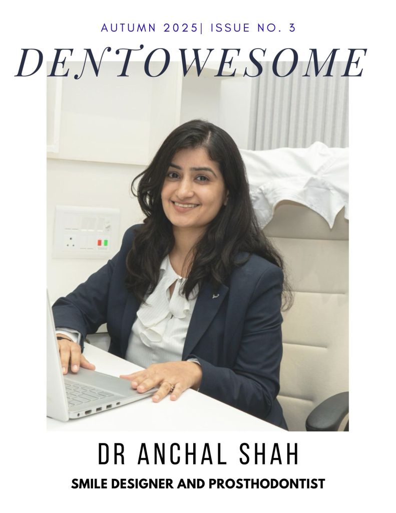
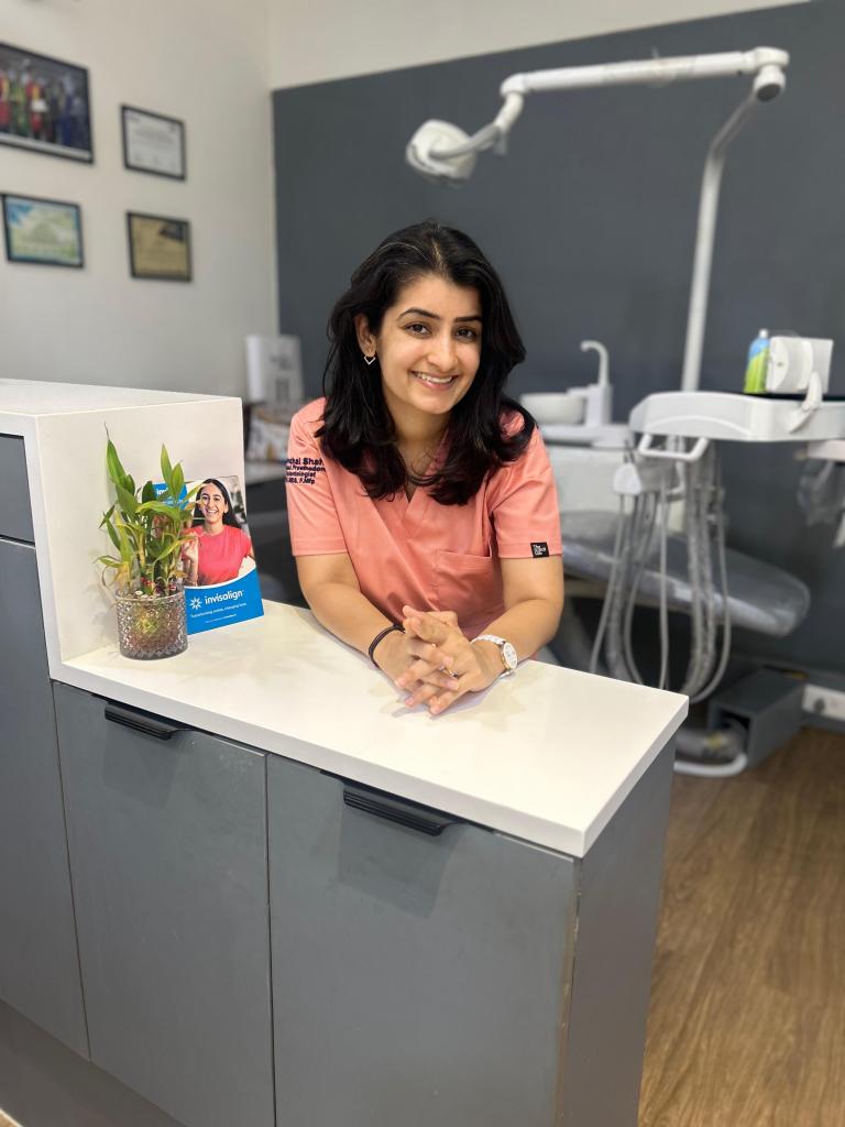
Every smile has a story, and so does every dentist who crafts them. In this exclusive conversation, we sit down with Dr. Anchal Shah, Prosthodontist at Dr. Shah’s Smile Studio, to learn about her inspiring journey—from a childhood fascination with chocolates to rebuilding lives through maxillofacial prosthetics.
1) Can you share how your path in the dental profession began and the key milestones that shaped it?
✨ Childhood: It’s funny how a simple love for chocolates led me toward a world I never imagined—dentistry. What began as curiosity slowly transformed into passion.
✨ BDS Days: The first two years were honestly tough. I often felt lost, wondering why I was spending hours working on baseplates or burning my fingers. But once clinics began, everything changed. I discovered joy in the smallest things—making dentures, performing extractions, or the adrenaline rush of placing my first suture.
✨ The Big Leap: I always dreamt of specializing in Prosthodontics. My first NEET MDS attempt didn’t work out, but I refused to give up. Taking a drop year was challenging, but it became one of the best decisions of my life. The effort paid off with AIR 66and admission to my dream college.
✨ Shaping My Purpose: Training under legends in Maxillofacial Prosthodontics gave me a mission bigger than myself—helping oral cancer survivors regain not just their smile, but their confidence and dignity.
✨ Where I Am Today: At Dr. Shah’s Smile Studio, I blend skill with compassion. My approach is holistic—every smile matters, every pain deserves care, and every patient’s story reminds me why I chose this path.
2) What inspires you to stay passionate and committed to dentistry, even during challenging times?
Dentistry, like life, isn’t always smooth. Some days are tough—when cases get complicated, outcomes don’t go as planned, or the weight of responsibility feels overwhelming.
On those days, I remind myself of two things:
🌱 How far I’ve come: From a confused BDS student burning my fingers on a baseplate to securing AIR 66 and finding my calling in Prosthodontics—every struggle has shaped me.
💡 Why I started: It was never just about teeth. It’s always been about people—their pain, their confidence, and their smiles. Watching a patient smile again after years is the kind of reward that keeps me going.
Every difficult moment becomes lighter when I remind myself of this: 👉 I didn’t come this far to give up. I came this far to make a difference
3) Who is your role model in the dental field and how has this person influenced your approach to patient care, academics, or professional growth?
I owe so much to my mentors.
• Dr. Rupal Shah, my postgraduate guide and Head of Department, taught me how much can be achieved with so little in hand. Her resourcefulness and patient-centered care continue to inspire my daily practice.
• Dr. P. C. Jacob, my mentor in oral cancer rehabilitation, showed me the power of perseverance and empathy in dealing with some of the most complex and emotionally demanding cases.
Their teachings shaped my outlook—not just as a clinician, but as a human being who believes in healing beyond treatment.
4) Could you discuss the strategies you use to manage academic responsibilities alongside your personal interests or hobbies?
Dentistry can easily consume your entire day, but I’ve learned that balance is key. Keeping my small passions alive keeps me grounded.
For me, it’s listening to podcasts, tuning into music, or watching a good movie. Podcasts give me new perspectives, music uplifts my mood instantly, and movies help me pause and reset.
Even 20–30 minutes a day can make a difference. You don’t need hours for hobbies—just intention. These little joys refill my energy, empathy, and creativity, helping me return to dentistry with a refreshed mind.
Because while dentistry defines my work, my hobbies remind me who I am.
5) What advice would you give to current dental students and aspiring dentists?
Don’t rush to have it all figured out. It’s completely normal to feel lost in the beginning—to question your path, or to wonder why you’re spending endless hours perfecting a baseplate or bending wires.
Trust the process. Those small, repetitive tasks are building your foundation—your patience, precision, and perseverance.
Stay consistent. Stay curious. And don’t fear setbacks. One exam, one failure, or one tough day doesn’t define your journey—your persistence does.
Most importantly, never forget why you started. Dentistry is not just about teeth—it’s about people, their confidence, and their smiles.
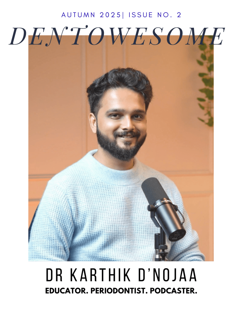
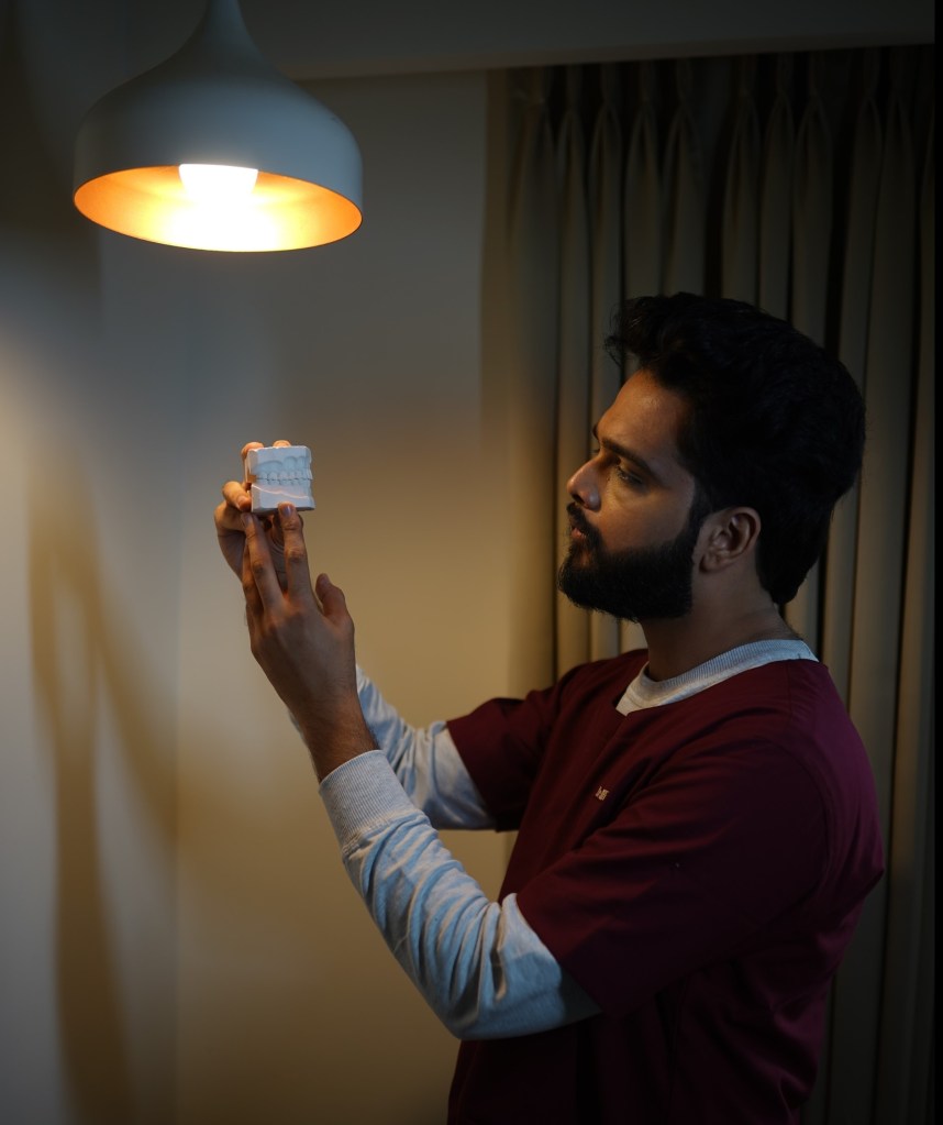
🎙️ From Scalpel to Spotlight: A Candid Chat with Dr. Karthik
MDS Periodontology | Educator | Host of the India’s Most Famous Dentist Podcast | Winner of the Golden Mic Award for Best Dental Podcast
If you’ve scrolled through dental Instagram lately or tuned into any student-friendly podcast, chances are you’ve come across Dr. Karthik. Known for his calm voice, creative visuals, and deep conversations on the India’s Most Famous Dentist Podcast, he’s someone who makes dentistry feel a little less intimidating—and a lot more inspiring.
We caught up with him to talk about his journey, his motivation, and his advice for the next generation of dentists.
🦷 Q1. So, Dr. Karthik—where did it all begin? What pulled you into dentistry?
I think I was always inclined toward the artistic side of things. Even before dentistry, I’ve had this natural urge to focus on precision and the smaller details – whether it was sketching, filmmaking, or editing. I’ve always believed that creativity and precision go hand in hand. Those who’ve seen my videos or podcast visuals probably notice that – my team and I put a lot of thought into how things look and feel, because I think dentistry is also an art form.
So for me, it wasn’t a trickle-down choice or a backup plan. Dentistry – and especially periodontics matched that part of me that loves design, structure, and creating something that lasts. It gave me a space where art, science, and communication meet – and that’s what continues to drive me every day.
I think I’ve always had this curiosity to understand how things work – especially the human body. During my early years, I could spend hours with anatomy, physiology, pharmacology, or medicine textbooks. They completely fed that curiosity of knowing how the body is designed and how it functions.
But soon, I realized that knowing wasn’t enough – I had this restless urge to do something with that knowledge. I’m a very hands-on, high-energy person, so I naturally gravitated toward dentistry. The pre-clinical labs – wax patterns, tooth carvings, crown preparations – all of that gave me a creative outlet.
Then came the clinical years – Conservative Dentistry, Prosthodontics, Periodontics, Oral Surgery, Orthodontics, Oral Medicine and Radiology, Pedodontics and Public health Dentistry – and that’s when I really found my rhythm. Periodontics especially connected deeply with me because it’s where precision meets biology. You can see what you’re working on, and every millimetre matters – it matched my personality perfectly.
Over time, those experiences shaped how I approach not just treatment, but also communication whether it’s through my podcast, my content, or my work with students and clinicians. Each phase was a milestone that built both the clinician and the creator in me.
💪 Q2. What keeps you going when the days get tough?
I always start with history. When you stay connected to your roots, it gives you a deep sense of value for what you have today.
If you look back, the pioneers of dentistry – the scientists, clinicians, researchers – they built this field with almost no resources. They worked for patient welfare, comfort, accessibility, and affordability, long before we had the kind of technology and conveniences we rely on now.
That perspective really keeps me grounded. Whenever I go through a challenging phase, I remind myself – we are walking on a path that so many before us have built through pure dedication and passion. All we need to do is keep that spirit alive.
In fact, this is something I often tell students: value what you have today, because it’s the result of decades of evolution. On my podcast, we’ve done a few episodes on the History of Dentistry -featuring experts and curators from dental museums, and even conversations on how dentistry was practiced in the 1950s compared to now. Those episodes truly help you appreciate how far we’ve come as a profession.
So, whenever I feel tired or demotivated, revisiting that history – the legacy of our field – reignites my purpose. It reminds me that being part of dentistry itself is a privilege.
🌟 Q3. Do you have a role model—or many?
Well, for me, it’s hard to name just one person as a role model. I’ve been fortunate to meet and learn from so many incredible dentists throughout my journey.
During my undergraduate days, I was very active in both curricular and extracurricular activities -which gave me the chance to interact with dentists who were doing outstanding work, nationally and internationally. Then in post-graduation, I think I must have attended over fifty national and international dental education programs. Each of those experiences connected me with mentors, clinicians, and researchers who were masters in their domains.
So for me, keeping just one role model has always been difficult. I try to stay alert and absorb something valuable from everyone I meet – because sometimes a small line of advice from an experienced dentist can be worth more than what you find in textbooks.
And on top of that, my podcast journey has been a huge source of learning. Every guest I’ve hosted – whether it’s Dr. Anuj Agarwal, Dr. Ashish Jain, Dr. Suresh Ludhwani, Dr. Moez Kahkiani, or someone like Dr. Sandesh Mayekar who’s contributed in all aspects – each of them has left a strong impression on me. I’ve learned a lot from their experiences, their perspectives, and even their attitude toward growth.
So, rather than one role model, I’d say I have many – and collectively, they keep me grounded, curious, and inspired to do better every day.
🎬 Q4. How do you juggle academics, practice, and content creation?
Yes, it has been challenging – but not because of lack of time or multitasking. The real challenge often comes from the mindset around us. Many people assume that if you’re doing something beyond your main work – like pursuing hobbies, content creation, or any parallel interest – you’re somehow not focused on your core field.
But that’s not true at all. That’s just a shallow perception. I genuinely believe that your hobbies and creative skills can strengthen your main profession, if you channel them in the right way. For me, filmmaking, editing, communication – all of these have actually helped me explain dentistry better and connect with people more effectively.
I once asked a very well-known businessman of our country – whose discussion will soon be out on my page – about how he managed to stay focused amid so much noise. He gave a brilliant analogy. He said, ‘In your generation, you have noise-cancellation headphones. I naturally developed the ability to switch my ears on and off – to only listen to what truly matters.’ That line really stayed with me.
And honestly, that’s the key. You have to learn to tune out the outer noise. Focus only on what adds value. Everyone has immense creativity, energy, and potential – it’s just the distractions that pull you back. If I have to put it as a strategy – I’d say: eat, sleep, do one thing for yourself, one for your family, and one for society – and repeat.
🪥 Q5. What’s your advice for dental students and young clinicians?
My advice would be simple – don’t just study dentistry, live it. Dentistry today isn’t only about clinical skills; it’s about how you think, how you communicate, and how you keep learning every single day. Be curious – not just about treatments, but about people. Understand your patients, listen to them, and value the privilege of being trusted with their health.
Secondly, don’t compare your journey with others. Everyone’s timeline is different. Some people bloom early, some take time – and both are absolutely fine. What matters is that you stay consistent and keep improving your craft.
Also, take your creative side seriously. Whether it’s content creation, design, research, or patient communication – your ideas and hobbies can actually strengthen the field if you channel them with purpose.
And lastly, always remember – this profession was built on service and sincerity. So stay grounded, stay ethical, and contribute back in your own way.
If I had to sum it up in one line, I’d say: Keep learning, stay curious, do good work – and life will give you more than you ever expected.
And yes, I’d genuinely encourage students and young dentists to watch my show – the guests we’ve had share incredible insights that can really shape how you look at the profession. And feel free to connect with me if you ever want to discuss ideas, to learn, or just want to talk – I’m always happy to interact with passionate minds. Thank you.
🎧 Before We Sign Off…
Dr. Karthik’s journey reminds us that being a dentist isn’t only about perfect crowns or precise sutures—it’s about storytelling, service, and staying curious.
If you’re ever in need of a dose of inspiration, tune in to his award-winning with India’s Most Famous Dentist (IMFD) Podcast—a space where students, clinicians, and even parents discover what the world of dentistry really looks like.
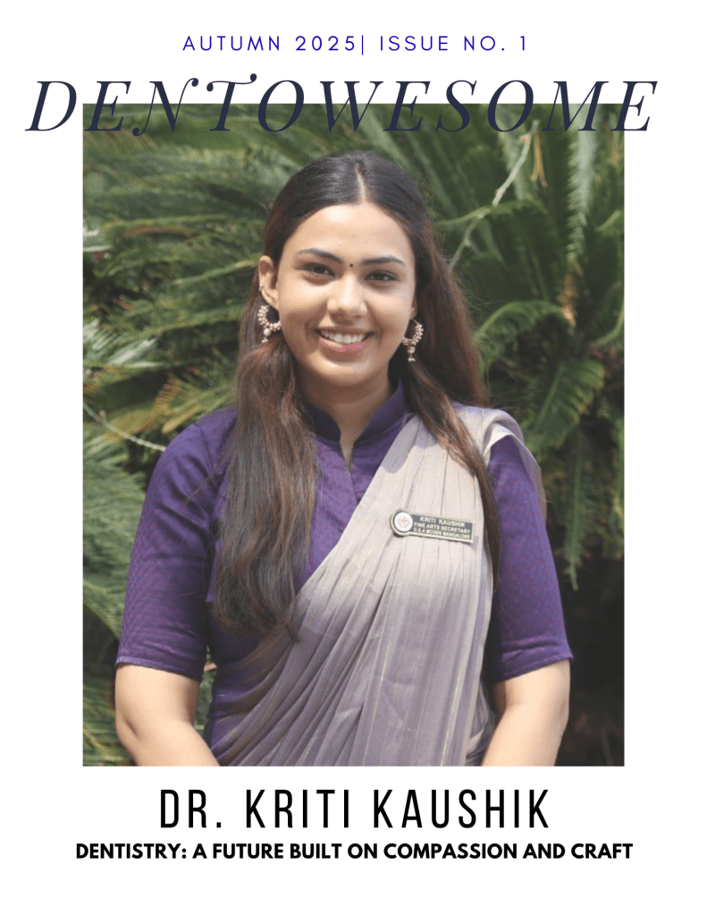
A candid interview about finding passion, purpose, and artistry in dentistry
The journey from aspiring doctor to dedicated dentist isn’t always straightforward. For this young prosthodontist, it was a path of discovery that revealed how art, science, and compassion can merge into a fulfilling career. We sat down to discuss her transformation from a hesitant dental student to a passionate professional who sees every patient as an opportunity to restore not just smiles, but confidence.
Finding Your Path: When Plans Change
Q: You’ve mentioned that you always wanted to be a doctor. How did you end up choosing dentistry, and what was that transition like?
I always wanted to be a doctor since childhood. After clearing NEET, I got into MCODS, Mangalore. I’ll be honest—at first, I wasn’t very happy about choosing dentistry. But over time, I realized its benefits. It offers a good work-life balance and the perfect mix of art and science, which suited me because I’ve always been into art. Now, I see dentistry as more than a career—it’s my way to combine creativity with helping people.
Defining Moments: The Making of a Prosthodontist
Q: What were the key experiences during your education that shaped your decision to specialize in prosthodontics?
Several moments really shaped my journey. Becoming the Fine Arts Secretary of my college boosted my creativity and leadership skills in ways I hadn’t expected. My internship year was transformative—gaining real patient experience changed everything for me. Publishing research articles and attending workshops expanded my horizons, but most importantly, it was the constant motivation from my professors to push myself that led me to choose prosthodontics.
The Heart of Practice: What Drives You
Q: Dentistry can be demanding. What keeps you passionate, especially during challenging times?
What keeps me passionate, even during challenging times, is seeing the change I can bring to a patient’s life. Sometimes it’s not just about relieving pain—it’s about restoring their confidence. That moment when a patient looks in the mirror, smiles, and you can see their whole expression change—that’s priceless. The satisfaction of knowing I played a part in that transformation keeps me motivated to give my best, no matter how difficult the day gets.
Lessons from a Mentor: The True Measure of Success
Q: Who has been your biggest inspiration in the field?
My role model is my professor, Dr. Shobha. She may not be a big name online, but to me, she represents everything a true dentist should be. She’s an outstanding prosthodontist, but what really inspires me is her kindness, her patience with students, and her uncompromising work ethics. No matter how busy she is, she treats every patient with the same level of care and attention. Seeing her passion for dentistry and the respect she earns from patients and colleagues has taught me that success in this field isn’t just about skill—it’s about heart. That’s the kind of dentist I aspire to be.
Balancing Act: Life Beyond the Clinic
Q: How do you manage to balance the demands of your profession with personal interests and wellbeing?
Time management is the key for me. I start by prioritizing tasks based on deadlines and importance, so my academic work is completed without last-minute stress. During busy periods, I break larger tasks into smaller, achievable goals, which helps me stay consistent. I also make sure to set aside time for my hobbies like painting and cooking because they give me a creative break and keep me mentally fresh. Balancing the two not only helps me stay productive but also keeps me motivated and happy in the long run.
Words of Wisdom: Advice for Aspiring Dentists
Q: What advice would you give to students who are just beginning their journey in dentistry?
Don’t overthink or compare your journey with others. Give yourself time to grow, prioritize your health, and keep learning every day. Dentistry is constantly evolving, so staying curious and open to new skills will always keep you ahead. And remember, dentistry is the future—there are endless opportunities if you’re willing to work for them.
As our conversation draws to a close, it’s clear that this young professional embodies the future of dentistry: technically skilled, artistically minded, and deeply compassionate. Her journey reminds us that the path to finding one’s calling isn’t always linear, but with the right mindset and mentors, it can lead to a career that transforms lives—both the patients’ and one’s own.
For decades, orthodontists have feared the words “open bite relapse.” We’ve all seen those post-surgical cases where the overbite slowly flattens out again, leaving both the clinician and the patient frustrated.
But recent evidence tells a more optimistic story. We looked at three landmark studies that prove surgical open bite correction can, in fact, stay stable long-term — if planned and executed correctly.
Let’s break it down 👇
🧠 Why Does Open Bite Relapse Happen?
Open bites often involve vertical skeletal discrepancies, soft-tissue imbalances, and habit-related influences (like tongue thrust or mouth breathing). Even after successful closure, relapse can creep in because of:
Posterior mandibular rotation post-surgery
Muscle and condylar adaptation
Incomplete control of incisor inclination
Prolonged vertical elastics or residual tongue posture
Understanding these helps us choose treatment options that offer the best long-term stability.
🔍 What Does the Evidence Show?
🔹 1. Bimaxillary Surgery: Fischer et al., 2000 (EJO)
This study followed 58 patients who underwent Le Fort I osteotomy + Bilateral Sagittal Split Osteotomy (BSSO) to correct open bite and mandibular retrognathism.
🩺 Findings after 2 years:
The maxilla stayed stable.
The mandible rotated back by only 1.4°, showing mild skeletal relapse.
17 patients developed a small open bite again, mostly due to incisor proclination, not jaw rotation.
The most stable results occurred in patients who had no post-op MMF (maxillomandibular fixation) — early mobilization helped muscles adapt better.
💡 Take-home: Rigid fixation + early mobilization = better stability.
🔹 2. Mandibular-Only Surgery: Fontes et al., 2012 (AJODO)
This study challenged the belief that we must operate on the maxilla for every open bite case. It followed 31 patients treated with BSSO and closing mandibular rotation only (no maxillary impaction).
📊 Results after 4.5 years:
Initial open bite: –2.6 mm
Surgical correction: +3.7° closing rotation of mandible
Long-term: 90% maintained positive overlap!
Even though about 60% of the rotation was lost, only 3 patients relapsed to zero overbite.
💡 Take-home: For mild-to-moderate skeletal open bites, mandibular-only surgery can be predictably stable and avoids unwanted soft-tissue changes (like widened nasal base or flattened upper lip).
3️⃣ Surgical vs. Nonsurgical Approaches – What’s More Stable?
Greenlee et al., 2011 — The Meta-Analysis That Ties It Together
This systematic review pooled data from 21 studies on open bite correction — both surgical and nonsurgical.
📈 The big picture:
Surgical treatments: ~82% stability (positive overbite ≥ 1 year post-op)
Nonsurgical treatments: ~75% stability
Average relapse in overbite: < 0.5 mm over 3–4 years
💡 Take-home: Both surgical and orthodontic approaches can be stable when case selection, fixation, and retention are well managed.
⚙️ Clinical Insights for Students
Focus Area
Key Point for Practice
Case selection
Choose surgical correction for true skeletal AOB with steep mandibular plane angles.
Avoid proclination of upper/lower incisors post-surgery.
MMF duration
Short or no MMF enhances functional recovery and stability.
Post-op care
Encourage physiotherapy and early functional movement.
Retention
Prolonged retention and habit control are essential to prevent vertical relapse.
Parameter
Pretreatment
Post-Surgery
Long-term Follow-up
Change/Relapse
Mean open bite (BSSO)
–2.6 mm
+1.4 mm
+1.0 mm
0.4 mm relapse
Mandibular rotation
+3.7° closing
–2.2° reopening (4.5 yrs)
60% rotation loss
Clinically stable outcome
Bimaxillary (Fischer et al.)
–0.9 mm
+2.2 mm
+0.8 mm
~1.4° mandibular reopening
Pooled (Meta-analysis)
–2.8 mm
+11.6 mm
+10.3 mm
82% maintained positive OB
References:
Fischer K, von Konow L, Brattström V. Eur J Orthod. 2000;22:711–718.
Fontes AM, et al. Am J Orthod Dentofacial Orthop. 2012;142:792–800.
Greenlee GM, et al. Am J Orthod Dentofacial Orthop. 2011;139:154–169.
🦷 Clinical-Oriented MCQs: Anterior Open Bite Stability After Surgery
1.
A 25-year-old female underwent bimaxillary surgery (Le Fort I impaction and BSSO) for anterior open bite. Two years later, her cephalometric evaluation shows a 1.4° posterior rotation of the mandible. What is the most likely reason for this relapse?
A. Condylar sag during fixation B. Maxillary relapse C. Incisor proclination and dentoalveolar compensation D. Nasal soft-tissue tension
✅ Answer: C. Incisor proclination and dentoalveolar compensation 🩺 Explanation: Fischer et al. (2000) reported that the mild relapse seen in 17/58 patients was primarily due to dental changes (incisor proclination), not skeletal instability.
2.
Which fixation method is most strongly associated with long-term stability in open bite surgery?
A. Wire osteosynthesis B. Rigid internal fixation using plates and monocortical screws C. Intermaxillary fixation for 8 weeks D. External pin fixation
✅ Answer: B. Rigid internal fixation using plates and monocortical screws 🩺 Explanation: Rigid fixation provides superior skeletal stability and minimizes posterior mandibular rotation. (Fischer et al., 2000; Fontes et al., 2012)
3.
In Fontes et al. (2012), which surgical technique was assessed for its long-term stability in anterior open bite correction?
A. Le Fort I impaction of the maxilla B. Bimaxillary osteotomy C. Bilateral sagittal split osteotomy (BSSO) with closing rotation of the mandible D. Segmental maxillary osteotomy
✅ Answer: C. Bilateral sagittal split osteotomy with closing rotation of the mandible 🩺 Explanation: The study specifically evaluated BSSO with rigid internal fixation and found 90% of patients maintained a positive overbite 4.5 years post-treatment.
4.
What was the long-term success rate (positive overbite ≥1 year post-op) for surgical open bite treatment according to Greenlee et al. (2011)?
A. 60% B. 70% C. 82% D. 90%
✅ Answer: C. 82% 🩺 Explanation: The meta-analysis reported an 82% success rate for surgical interventions and 75% for nonsurgical treatment in maintaining positive overbite.
5.
During open bite correction, which factor most increases the risk of relapse due to soft tissue and muscular tension?
A. Steep mandibular plane angle B. Reduced condylar height C. Excessive mandibular closing rotation (>4°) D. Small gonial angle
✅ Answer: C. Excessive mandibular closing rotation (>4°) 🩺 Explanation: Over-rotation increases muscular stretch and pterygoid tension, contributing to relapse (Fontes et al., 2012).
6.
Which postoperative protocol demonstrated the most favorable stability outcomes in bimaxillary surgery cases?
A. 8-week maxillomandibular fixation B. 1–3 weeks of MMF C. No MMF with early mobilization D. Rigid fixation followed by elastic traction
✅ Answer: C. No MMF with early mobilization 🩺 Explanation: Fischer et al. (2000) found the most stable overbite in patients without MMF, suggesting early mobilization promotes muscle adaptation and healing.
7.
In mandibular-only surgery for open bite, approximately what percentage of surgical closing rotation is typically lost long-term?
A. 10% B. 30% C. 60% D. 80%
✅ Answer: C. 60% 🩺 Explanation: Fontes et al. (2012) reported that about 60% of the mandibular closing rotation achieved at surgery was lost, yet functional overlap was maintained.
8.
Which cephalometric parameter was significantly correlated with open bite relapse post-surgery?
A. ANB angle B. SN–ML angle (mandibular plane angle) C. U1–L1 interincisal angle D. SNA angle
✅ Answer: B. SN–ML angle 🩺 Explanation: Increased mandibular plane angles are associated with vertical skeletal patterns that predispose to relapse (Fischer et al., 2000).
9.
Why might mandibular-only BSSO be preferred over maxillary impaction surgery in some open bite cases?
A. It allows greater anterior movement of the maxilla B. It produces fewer unfavorable nasal and upper lip changes C. It reduces operation time by half D. It eliminates the need for orthodontic finishing
✅ Answer: B. It produces fewer unfavorable nasal and upper lip changes 🩺 Explanation: Fontes et al. (2012) noted mandibular-only correction avoids side effects like nasal widening, upper lip thinning, and excessive gingival display.
10.
Which of the following best summarizes the long-term evidence on open bite surgical stability?
A. Relapse is inevitable due to vertical muscle pull. B. Only bimaxillary surgery yields stable results. C. Both surgical and nonsurgical approaches show >75% long-term stability. D. Stability depends only on orthodontic retention.
✅ Answer: C. Both surgical and nonsurgical approaches show >75% long-term stability. 🩺 Explanation: Greenlee et al. (2011) meta-analysis found 82% stability for surgical and 75% for nonsurgical corrections at ≥1-year follow-up.