Avoids morbidity of Le Fort I and bimaxillary procedures.
Aesthetic gain: enhances chin prominence, may eliminate need for genioplasty.
Best suited for selected cases — not all open bites.
6️⃣ Summary Recommendation
In carefully selected Class II AOB cases with normal maxilla and retrogenia, mandibular anticlockwise rotation via MSSO offers stability comparable to maxillary impaction, with reduced surgical morbidity.
Traditional approach: Maxillary impaction (LeFort I) was standard for open-bite correction due to instability of early mandibular-only approaches.
Current advancement: Rigid internal fixation allows mandibular-only surgery using bilateral sagittal split osteotomy (BSSO) with counterclockwise rotation of the distal segment.
2️⃣ Surgical Concept
Step
Description
Presurgical orthodontics
Level maxillary arch via maxillary incisor extrusion → creates level occlusal plane for mandibular autorotation.
Osteotomy
Bilateral sagittal split osteotomy with counterclockwise rotation of mandibular distal segment.
Fixation
Rigid internal fixation using 4 screws per side.
Objective
Establish positive overbite/overjet with stable posterior occlusion.
3️⃣ Indications
Moderate anterior open bite (6–7 mm)
Patients where maxillary impaction undesirable (esthetic concerns, nasal morphology)
When cost or morbidity of double-jaw surgery is to be minimized
➡ Mandibular osteotomy shows equal or better long-term stability.
6️⃣ Key Clinical Pearls
Maintain stable incisor extrusion before surgery—no significant relapse noted.
Ensure level occlusal plane before rotation to prevent posterior open bite.
Rigid fixation is critical for stability.
Post-op orthodontic detailing essential for final intercuspation.
7️⃣ Limitations / Cautions
⚠ Not suitable for severe open bites (>7–8 mm) or complex vertical discrepancies. ⚠ Limited long-term data; ongoing follow-up advised. ⚠ Requires precise planning of occlusal plane leveling to prevent over-rotation.
8️⃣ Clinical Summary
Mandibular counterclockwise rotation via BSSO is a viable and stable alternative to maxillary impaction for moderate anterior open-bite correction, providing both esthetic and economic benefits.
Palatal miniscrews provide reliable intraoral anchorage for distalization and expansion while minimizing compliance issues and anchorage loss, making them foundational in modern biomechanics.
🩺 Clinical Objective
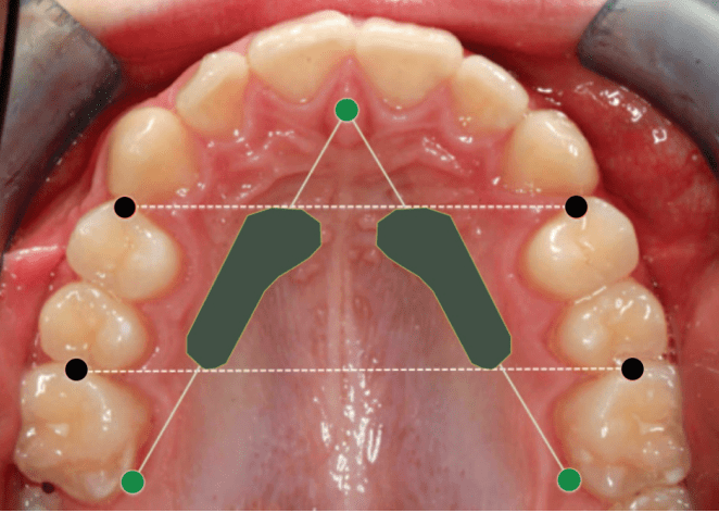
Identify safe and reliable sites for orthodontic mini-implant (OMI) insertion in the paramedian anterior palate based on vertical bone height (VBH) and anatomical safety.
📍 Optimal Insertion Zone
Reference Point
Safe Zone Coordinates
Average VBH (mm)
Remarks
From incisive foramen
3–4 mm posterior
7–11 mm
Consistent adequate bone height
From midpalatal suture
3–9 mm lateral
≥5 mm (safe minimum)
Ideal for OMI placement
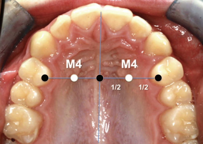
M4 Site (Winsauer et al., 2011)
3 mm AP, 6 mm ML
10–11 mm
Preferred site for molar distalizers
Posterior to 12 mm
9–12 mm lateral
4–5 mm
Diminishing VBH; use with caution
Note: “M4 site” — halfway from midpalatal suture to the first premolar along the line through the palatal cusp of the first premolar
🧭 Insertion Guidelines
Implant size: 2.0 mm diameter, 10–14 mm length
Minimum VBH required: ≥ 5 mm
Insertion direction: Perpendicular to palatal surface
Pre-check: Lateral ceph or CBCT (especially in thin palates)
Avoid: Midpalatal suture in growing patients (growth disturbance risk)
🧫 Mucosal Considerations(Marquezan et al., 2012)
Palatal mucosa is thickest anterolaterally; estimate with an LA needle and stop (rubber disc) to plan trans-mucosal length and ensure adequate intraosseous purchase.
Engaging both cortical plates (where feasible) decreases trabecular stress and enhances primary stability, but even single-cortex engagement with adequate VBH supports orthodontic load ranges.
Site (AP × ML)
Mucosal Thickness (mm)
4 × 6 mm
5.26
8 × 6 mm
4.39
4 × 3 mm
3.37
8 × 3 mm
2.71
Thicker keratinized mucosa at paramedian regions reduces infection and inflammation risk.
⚠️ Anatomical & Safety Notes
Safe region: AP 3–9 mm, ML 3–9 mm (anterior paramedian zone)
Arteria palatina: Rarely encountered and thin
Risk of nasal perforation: Minimal if CBCT verified
Preferred for:
Molar distalizers
Hybrid expanders (e.g., Hyrax)
Absolute anchorage appliances
📊 Bone Density Summary
Location
Bone Density
Clinical Relevance
3 mm lateral to suture
> 50–70 % hard tissue fraction
High stability potential
Posterior regions
Decreasing density
Use caution
🦷 Clinical Scenario–Based MCQs
Q1. Site Selection & Risk Avoidance
A 17-year-old female requires anchorage for bilateral molar distalization. You plan mini-implant placement in the anterior palate. Which insertion site minimizes risk of nasopalatine canal injury while ensuring adequate vertical bone height (VBH)? A. 1 mm posterior to incisive foramen, 2 mm lateral to midpalatal suture B. 3–4 mm posterior to incisive foramen, 3–9 mm lateral to suture C. 8–10 mm posterior to incisive foramen, 12 mm lateral to suture D. Midpalatal suture at canine level
Answer: ✅ B. Explanation: The safe paramedian zone (AP 3–4 mm, ML 3–9 mm) provides ≥ 5 mm VBH and avoids the incisive foramen.
Q2. Growth Consideration
In a 12-year-old patient, you consider midpalatal placement of mini-implants. Which is the primary concern? A. Thin cortical bone B. High mucosal thickness C. Risk of interfering with midpalatal suture growth D. Perforation into nasal floor
Answer: ✅ C. Explanation: The midpalatal suture may ossify variably up to late adolescence; premature insertion can disturb transverse growth (Asscherickx et al., 2005).
Q3. Imaging Decision
Routine lateral cephalogram shows limited palatal height near the first premolar line. What is the most appropriate next diagnostic step before insertion? A. Proceed using standard depth screw B. Use intraoral periapical radiograph C. Request CBCT for precise VBH assessment D. Probe mucosa to estimate bone depth
Answer: ✅ C. Explanation: CBCT provides accurate 3D VBH estimation and should be used when cephalogram suggests borderline bone height.
Q4. Implant Stability
A clinician inserts a 2 mm diameter, 10 mm length screw into an area with 4 mm VBH. What is the likely clinical outcome? A. Adequate anchorage B. Reduced initial stability and possible failure C. Excessive soft-tissue coverage D. Root contact with lateral incisor
Answer: ✅ B. Explanation: Minimum 5 mm bony support is essential for stability against 0.5–3 N orthodontic forces; < 5 mm risks loosening.
Q5. Safe Depth Estimation
During anesthesia, the clinician probes mucosal thickness using the injection needle and finds 4.5 mm. If the CBCT indicates VBH of 8 mm at that site, what is the safe insertion length? A. 8 mm B. 10 mm C. 12 mm D. 14 mm
Answer: ✅ B. Explanation: Total tissue = mucosa + bone ≈ 12.5 mm; a 10 mm implant ensures bony engagement without nasal floor perforation.
Q6. Bone Quality vs. Quantity
A patient shows high VBH (10 mm) but low bone density in posterior palate. What is the best site for improved cortical engagement? A. Posterior palate near first molars B. Anterior paramedian palate (AP 3–6 mm, ML 3–6 mm) C. Midpalatal suture D. 12 mm lateral to suture
Answer: ✅ B. Explanation: The anterior paramedian palate has thicker cortical bone and higher density, improving primary stability.
Q7. Variability and Imaging Rationale
Despite the review identifying an ideal zone, why is routine individual imaging still recommended? A. Studies showed consistent VBH across all patients B. VBH strongly correlates with age alone C. Great inter-individual variability in palatal bone height exists D. Cephalometry alone can reliably measure VBH
Answer: ✅ C. Explanation: Substantial anatomical variability necessitates individualized imaging (CBCT) for safety and accuracy.
Q8. Surgical Risk Awareness
If a screw is inserted blindly to 8 mm depth at AP 9 mm / ML 9 mm in an adult, which complication is most likely? A. Root perforation B. Nasal cavity penetration C. Sinus floor damage D. Palatal artery laceration
Answer: ✅ B. Explanation: Beyond AP 9 mm, VBH often falls below 5 mm; deep insertion risks nasal perforation.
Q9. Cortical Involvement
Why does engaging both cortical plates enhance implant stability compared to single-layer cortical anchorage? A. Reduces trabecular compression stress B. Promotes faster osseointegration C. Reduces mucosal overgrowth D. Prevents micro-motion entirely
Answer: ✅ A. Explanation: Dual cortical anchorage distributes stress and enhances mechanical resistance under orthodontic load (Kim et al., 2006).
Q10. Clinical Application
For a TopJet molar distalizer, which insertion site is ideal according to Winsauer et al. (2012)? A. 6 mm posterior to incisive foramen, 12 mm lateral to midline B. 3 mm posterior and 6 mm lateral to midpalatal suture (M4 site) C. Directly over midpalatal suture at premolar level D. 10 mm posterior, 9 mm lateral to midline
Answer: ✅ B. Explanation: The M4 site (AP 3 mm, ML 6 mm) lies within the area of maximal VBH, offering safe, stable anchorage for molar distalization.
1) Always clinically assess mandibular posture and function before deciding on a treatment plan. Static records like cephs or models don’t reveal functional disturbances.
2) Functional retroversion must be confirmed through both clinical and radiographic evaluations, supported by deprogramming splints to identify true mandibular position.
3) Functional appliance therapy is effective only when favorable growth potential exists. Evaluate skeletal maturity using Bjork’s structural signs and Schwarz analysis.
4) Overjet alone should not dictate functional treatment. Use molar relationship and skeletal base assessments as the true determinants for mandibular advancement.
5) Choose the functional or corrective appliance based on diagnostic needs—not habit or routine. Understand each appliance’s biomechanical goals before use.
6) Utilize Schwarz craniometry to evaluate maxillary and mandibular base adequacy. This helps judge whether a patient truly requires mandibular advancement or other skeletal correction.
7) Extreme incisor inclinations or unusual bite patterns often arise from environmental factors (e.g., thumb sucking, tongue habits), not inherent skeletal patterns.
8) Deep bites may develop from tongue or digit-sucking habits causing abnormal eruption paths. Correct these habits before addressing skeletal or dental compensation.
9) Always interpret subdivision or asymmetry cases with both dental and skeletal perspectives. Functional shifts, not just skeletal discrepancies, often drive asymmetries.
10) Prioritize correcting functional disturbances and establishing equilibrium before applying mechanical corrections or considering surgical interventions.
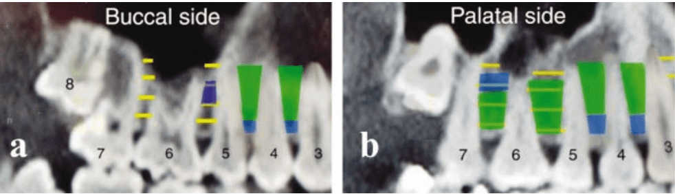
Interradicular anatomy limits where miniscrews can be placed without root proximity or sinus encroachment, making mesiodistal space the key parameter over buccolingual thickness.
Safe placement reduces root contact, improves primary stability, and avoids sinus and tuberosity pitfalls in the maxilla
📌 General Guidelines
Preferred screw diameter: 1.2–1.5 mm (safe clearance: ≥1 mm bone around screw).
Thread length: 6–8 mm, conical shape recommended.
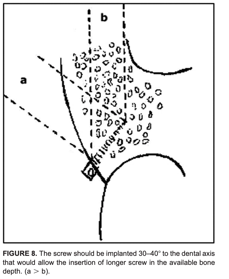
Insertion angle: 30–40° to long axis of tooth → more bone engagement, less root risk.
Avoid: Tuberosity, >8 mm above alveolar crest in maxilla (sinus risk), very close root proximity sites.
MAXILLA
Interradicular Site
Depth from Crest
Safety
Notes
6–5 (1st Molar–2nd PM, Palatal)
2–8 mm
🟢 SAFE
Best site
7–6 (2nd–1st Molar, Palatal)
2–5 mm
🟢 SAFE
Avoid >8 mm (sinus)
5–4 (2nd–1st PM)
5–11 mm
🟢 SAFE
Both buccal & palatal
4–3 (1st PM–Canine)
5–11 mm
🟢 SAFE
Both buccal & palatal
6–5 (Buccal)
5–8 mm
🟡 Limited
Narrow mesiodistal space
Tuberosity
Any
🔴 UNSAFE
Thin bone, sinus, 8s
Key maxillary insights 🦴
Palatal side offers more safe space than buccal, especially between 6–5 and 7–6 within 2–8 mm from the crest.
Avoid 8–11 mm apical to crest in posterior maxilla due to frequent sinus proximity; tuberosity is generally inadequate unless third molars are absent and bone is verified.
MANDIBLE
Interradicular Site
Depth from Crest
Safety
Notes
7–6 (2nd–1st Molar)
8–11 mm
🟢 SAFE
Best site
5–4 (2nd–1st PM)
All depths
🟢 SAFE
Consistently wide
6–5 (1st Molar–2nd PM)
11 mm
🟡 Limited
Shallow = risk
4–3 (1st PM–Canine)
11 mm
🟡 Limited
Safe only apically
4–3 (2–5 mm)
🔴 UNSAFE
Very close roots
Key mandibular insights 🦴
Safest sites: 7–6 and 5–4 across depths; 6–5 improves at deeper levels; 4–3 is tight and safer from 8–11 mm.
Buccolingual thickness is generous posteriorly, but mesiodistal spacing still dictates feasibility.
Depth logic mnemonic
“Two–to–Eight for Maxilla, Eight–to–Eleven for Mandible.”
Maxilla safer band: 2–8 mm near crest.
Mandible safer band: 8–11 mm deeper.
Diameter clearance mnemonic
“Diameter plus Double.”
Required mesiodistal space ≈ screw diameter + 2 mm total clearance.
Clinical decision pathway 🧠
Step 1: Select region by biomechanics; favor palatal 6–5 or 7–6 in maxilla and 7–6 or 5–4 in mandible.
Step 2: Choose depth band where mesiodistal space meets diameter + 2 mm clearance rule; avoid maxillary posterior >8 mm.
Step 3: Plan 30–40° insertion path with conical screw to maximize safe thread length and minimize root risk.
Step 4: Confirm with radiographic assessment in every case; population averages do not replace patient‑specific imaging.
Scenario 1: Maxillary site and depth
A 19-year-old with bilateral Class I crowding needs anterior retraction with absolute anchorage. Planned site: interradicular, maxillary right 6–5. Which depth window minimizes sinus risk while maximizing mesiodistal clearance?
A. 0–2 mm from crest B. 2–8 mm from crest C. 8–11 mm from crest D. >11 mm from crest
Answer: B Rationale: Palatal 6–5 offers the greatest mesiodistal space at 2–8 mm; posterior maxilla beyond ~8 mm risks sinus proximity and narrowing interradicular space. Takeaway: Choose 2–8 mm for maxillary posterior interradicular placement; avoid deep apical insertion due to sinus.
Scenario 2: Mandibular posterior preference
A 22-year-old requires lower incisor intrusion and posterior anchorage. Best interradicular site in the mandible for consistent mesiodistal space?
A. 4–3 at 2–5 mm B. 6–5 at 2–5 mm C. 5–4 across 2–11 mm D. 7–6 at 2–5 mm
Answer: C Rationale: 5–4 is reliably favorable across depths; 7–6 is safest deeper (8–11 mm), while 4–3 is tight near crest. Takeaway: Prefer 5–4 broadly; use 7–6 when inserting deeper (8–11 mm).
Scenario 3: Diameter and clearance rule
Planning a 1.5 mm conical miniscrew interradicularly. Minimum mesiodistal width to satisfy “diameter plus double” clearance?
A. 2.0 mm B. 2.5 mm C. 3.0 mm D. 3.5 mm
Answer: D Rationale: Approximate rule: screw diameter + 2.0 mm total clearance; 1.5 + 2.0 = 3.5 mm. Takeaway: For 1.5 mm screws, target ≥3.5 mm mesiodistal space.
Scenario 4: Angulation choice
A resident plans perpendicular insertion between maxillary 6–5 to maximize cortical engagement. What is the best correction?
A. Maintain perpendicular, use longer screw B. Angle 30–40° to the long axis to lengthen the safe path C. Shift to tuberosity to avoid roots D. Use 2.0 mm diameter to improve stability
Answer: B Rationale: 30–40° increases safe trans-cortical path and reduces early root proximity compared with perpendicular insertion. Takeaway: Favor 30–40° to the tooth axis in interradicular sites.
Scenario 5: Palatal posterior caution
During palatal placement near 7–6, the plan is to embed 10–12 mm for maximum stability. Best revision?
A. Maintain depth; palatal roots diverge widely B. Reduce to ~6–8 mm embedding to avoid buccal root convergence C. Switch to perpendicular insertion to stay central D. Increase diameter to 2.0 mm to improve purchase
Answer: B Rationale: Palatal roots allow space initially, but buccal roots converge; keep embedding around 6–8 mm with angulation. Takeaway: In palatal posterior, limit depth and use oblique path.
Scenario 6: Buccal 7–6 in the maxilla
A plan is made for buccal 7–6, 5 mm from crest, 1.5 mm screw. What is the primary risk?
A. Buccal plate perforation B. Infringement of the maxillary sinus at 5 mm C. Narrow mesiodistal interradicular clearance compared to palatal D. Insufficient buccopalatal cortical thickness
Answer: C Rationale: Buccal 7–6 has narrower mesiodistal space than palatal; clearance is the limiting factor. Takeaway: Mesiodistal width dictates feasibility more than buccolingual thickness.
Scenario 7: Immediate placement torque
In dense mandibular bone, a self-drilling miniscrew shows high insertion torque approaching fracture. Best intraoperative adjustment?
A. Increase hand torque to seat fully B. Switch to pre-drilling (pilot) to lower torsional stress C. Upsize to 2.0 mm diameter D. Angle perpendicular to reduce resistance
Answer: B Rationale: Pre-drilling reduces insertion torque and fracture risk in dense bone while preserving stability. Takeaway: Manage torque with pilot drilling in high-density bone.
Scenario 8: Root contact cue
During insertion, the driver suddenly stalls and higher force is needed; patient reports sharp sensitivity despite topical anesthesia. Next step?
A. Continue inserting to pass the tight spot B. Reverse 1–2 turns and redirect trajectory C. Switch to a longer screw D. Load immediately to test stability
Answer: B Rationale: Stall/sensitivity suggests PDL/root proximity; back out and redirect to avoid injury. Takeaway: Recognize tactile and patient cues of root contact; reposition immediately.
Scenario 9: Palatal anterior boundary
A miniscrew is planned at the second palatal rugae for retraction anchorage. What is the safer adjustment?
A. Move anteriorly for thicker cortical bone B. Place posteriorly at or behind the third palatal rugae C. Shift to infrazygomatic crest routinely D. Increase diameter to 2.0 mm for stability
Answer: B Rationale: Anterior palatal placements at/near second rugae risk root injury; safer zone is at/behind third rugae. Takeaway: Respect anterior palatal boundaries to avoid incisor root injury.
Scenario 10: Postoperative soft-tissue issues
A patient returns with mucosal overgrowth and peri-implant inflammation around a stable miniscrew. Best management?
A. Immediate removal of the miniscrew B. Debride, add a low-profile healing collar or spacer, reinforce hygiene, and consider chlorhexidine C. Load more heavily to reduce movement D. Ignore unless painful
Answer: B Rationale: Overgrowth and inflammation respond to local hygiene measures, soft-tissue management, and contour optimization; removal is not first-line if stable. Takeaway: Manage soft tissues proactively to maintain stability.
Scenario 11: Choosing between sites
Needing maxillary anchorage but palatal vault is shallow; CBCT shows limited palatal bone near 6–5. Best alternative?
A. Buccal 7–6 at 11 mm depth B. Buccal 6–5 at 5–8 mm depth with oblique angulation C. Tuberosity interradicular site D. Anterior palatal at second rugae
Answer: B Rationale: Buccal 6–5 mid-depth can be acceptable with careful angulation and clearance assessment; 11 mm posterior risks sinus. Takeaway: When palatal is limited, use buccal 6–5 at mid-depths with precise planning.
Scenario 12: Stability factor prioritization
Which factor most consistently correlates with miniscrew stability in interradicular sites?
A. Screw length alone B. Screw diameter and cortical thickness, plus soft-tissue health C. Patient age and sex D. Immediate loading is contraindicated
Answer: B Rationale: Diameter, cortical engagement, and inflammation control are key; length alone is less predictive, and immediate loading can be acceptable with good primary stability. Takeaway: Optimize diameter/site quality and soft-tissue health for stability.
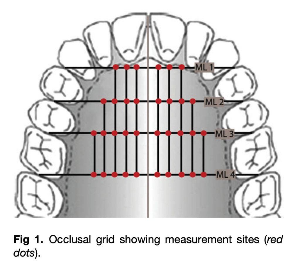
Primary stability and safety for palatal TADs depend on two anatomic variables: overall bone depth (BD) to avoid nasal perforation and cortical bone thickness (CBT) to achieve adequate insertion torque and stability. BD and CBT vary systematically across the palate, so site choice—not just screw design—drives success and risk mitigation in everyday mechanics.
Measurement Levels (MLs)
ML1: Canine–1st premolar
ML2: 1st–2nd premolars
ML3: 2nd premolar–1st molar
ML4: 1st–2nd molars
Key Principles
Bone Depth (BD): Greatest in anterior palate, decreases posteriorly.
Cortical Bone Thickness (CBT): Highest anteriorly, decreases posteriorly.
Primary Stability: Requires CBT > 1 mm for acceptable success.
Safe Implant Length:
Anterior (ML1 & ML2): 6–8 mm implants generally safe.
Posterior (ML3 & ML4): Risk of nasal perforation if ≥6 mm fully seated.
Bone Depth (BD) – Mean values (mm)
Level (ML)
2 mm
4 mm
6 mm
8 mm
10 mm
Zone
ML 1
8.7
7.6
7.3
—
—
🟢
ML 2
8.7
8.0
7.5
8.2
—
🟢
ML 3
4.3
3.9
3.7
4.1
5.3
🟡
ML 4
2.7
2.0
1.6
1.6
2.4
🔴
Safe depth for ≥6 mm TAD is reliably found only at ML 1 & ML 2.
Cortical Bone Thickness (CBT) – Mean values (mm)
Level (ML)
Mean CBT (mm)
Range
Zone
ML 1
1.49
0.65–2.43
🟢
ML 2
1.14
0.13–1.97
🟢
ML 3
1.04
0.10–2.78
🟡
ML 4
1.00
0.30–2.04
🟡/🔴
≥1 mm cortical thickness recommended for stability.
Quick Placement Guide
🟢 Best sites: Paramedian ML 1 & ML 2 (safe, accessible, adequate BD + CBT)
🟡 Variable sites: ML 3 (borderline, confirm with CBCT; angle placement if used)
🔴 Avoid: ML 4 (thin bone, risk of perforation, thick soft tissue, vessels nearby)
⚠️ Anterior caution: Stay clear of incisive canal (midline → only parasagittal placement)
💡 Trick: Angulated placement ↑ available BD in posterior palate
MCQs
The most favorable default site for palatal miniscrew placement in adults is:
A. Midline at incisive papilla
B. Paramedian at premolar level (ML1–ML2)
C. Paramedian at molar level (ML4)
D. Far lateral palate near greater palatine foramen Answer: B Rationale: Anterior paramedian sites (premolar region) combine higher bone depth with thicker cortex and easier access, reducing perforation and stability risks.
Which pattern best describes palatal bone depth (BD) across adults?
A. Increases posteriorly and laterally
B. Decreases posteriorly and laterally
C. Constant across all levels
D. Highest at molar level Answer: B Rationale: BD trends highest anteriorly near the midline and declines toward posterior and lateral regions.
For reliable primary stability of orthodontic miniscrews, a practical cortical bone thickness (CBT) threshold is:
A. ~0.3 mm
B. ~0.7 mm
C. ~1.0 mm or more
D. >2.5 mm always required Answer: C Rationale: About 1.0 mm CBT supports favorable insertion torque and stability without excessive site trauma.
To reduce perforation risk for a posterior paramedian placement without CBCT, the most sensible tactic is:
A. Use longer screws (≥8 mm) and seat fully
B. Perpendicular insertion with full seating
C. Angulate insertion and/or accept partial seating
D. Shift to the midsagittal plane Answer: C Rationale: Angulation increases traversed bone; partial seating reduces unintended nasal entry when BD is borderline.
Regarding the incisive canal, safer placement strategy is:
A. Sagittal midline at ML1
B. Paramedian at ML1–ML2
C. Midline further posterior
D. Crossing incisive papilla intentionally Answer: B Rationale: Paramedian avoids nasopalatine canal while preserving favorable BD/CBT.
A key anatomic hazard in the posterolateral palate is the:
A. Lesser palatine artery
B. Greater palatine neurovascular bundle
C. Infraorbital nerve
D. Nasopalatine nerve Answer: B Rationale: The greater palatine bundle courses posterolaterally and must be respected.
During insertion, approaching the nasal floor is often signaled by:
A. Sudden loss of torque
B. Soft tissue blanching alone
C. Firm “stop” from dense nasal cortical plate
D. Immediate gingival bleeding Answer: C Rationale: The dense nasal cortex provides distinct tactile resistance with slow, controlled placement.
Typical mean BD at ML4 (molar-level paramedian) is:
A. >8 mm
B. 5–6 mm
C. 2–4 mm
D. <1 mm Answer: C Rationale: Posterior paramedian BD is often shallow, making fully seated 6 mm screws risky.
Adult left–right differences in palatal BD/CBT are generally:
A. Large and significant
B. Significant only in females
C. Small and not statistically significant
D. Left always greater than right Answer: C Rationale: Side differences are typically negligible compared to anterior–posterior patterns.
Immediate loading feasibility most closely relates to:
A. Soft tissue thickness
B. CBT and insertion torque
C. Screw head shape
D. Chronologic age alone Answer: B Rationale: Cortical thickness drives insertion torque, which underpins primary stability for loading.
A practical default screw length for anterior paramedian adult palate is:
A. 4 mm
B. 6 mm
C. 10 mm
D. 12 mm Answer: B Rationale: Around 6 mm balances safety and stability in typical anterior paramedian BD.
Completely seating a 6 mm screw at ML4 commonly:
A. Is always safe
B. Risks nasal perforation
C. Causes mucoceles routinely
D. Increases CBT Answer: B Rationale: Shallow posterior BD increases perforation risk with full seating.
Management of a small nasal perforation during palatal TAD placement generally involves:
A. Mandatory surgical closure
B. Immediate removal plus nasal packing in all cases
C. Conservative observation; most heal uneventfully
D. Systemic steroids Answer: C Rationale: Small perforations usually resolve; escalate only if symptomatic.
The midsagittal suture is often excluded from generalized site recommendations because:
A. CBCT artifacts dominate
B. High anatomic variability across adults
C. No cortical plate exists there
D. It cannot be measured Answer: B Rationale: Suture variability undermines generalized midline guidance.
The single strongest driver of miniscrew design/length selection is:
A. Aesthetics
B. Brand
C. Placement site (location)
D. Patient preference Answer: C Rationale: Local anatomy dictates diameter, length, and thread engagement strategy.
Temporary anchorage devices enable controlled tooth movements such as anterior retraction, molar intrusion/distalization, nonsurgical open‑bite correction, and cant correction with simple placement, immediate loading, and minimal morbidity compared with plates or implants.
Preferred vertical level: 4 mm from CEJ (attached gingiva zone)
Anterior regions: Require subapical placement (≥ 6–8 mm from CEJ)
Posterior regions: Often safe at 4 mm; angulation increases clearance and cortical support
Placement angulation:
Straight/perpendicular in premolar and subapical anterior regions
Oblique/angulated in intermolar regions for safety
✅ COLOR LEGEND
🟢 SAFE: Adequate mesiodistal space (≥3 mm) & safety depth
🟡 CAUTION: Limited space; angulation or subapical placement needed
🔴 AVOID: Insufficient space, high root risk
📍 MAXILLA
Region (Teeth)
Level from CEJ
Safety
Notes
Central incisors
8 mm
🟡
Subapical/equiapical only
Lateral incisor – Canine
8 mm
🟡
Narrow at CEJ; safer apically
Canine – 1st premolar
6 mm
🟢
Reliable site
1st – 2nd premolars
4 mm
🟢
Consistently safe
2nd premolar – 1st molar
4 mm
🟢
Best interdental space
1st – 2nd molars
4–6 mm
🟡
Angulated placement advised
📍 MANDIBLE
Region (Teeth)
Level from CEJ
Safety
Notes
Anterior incisors
Any
🔴
Avoid interradicular; only true subapical
Lateral incisor – Canine
4–6 mm
🔴
Space ❤ mm
1st – 2nd premolars
4 mm
🟢
Most reliable site
2nd premolar – 1st molar
4 mm
🟢
Consistently safe
1st – 2nd molars
4–6 mm
🟢/🟡
Safe; angulation may help for group distalization
Reference: Lee KJ, et al. Computed tomographic analysis of tooth-bearing alveolar bone for orthodontic miniscrew placement.AJODO. 2009;135:486–94.
🦷 CLINICAL MCQs – Miniscrew Placement (Based on Lee et al., AJODO 2009)
Section A – Clinical MCQs (Single Best Answer)
A 25-year-old patient requires intrusion of maxillary central incisors. Based on CT evidence, the safest site for miniscrew placement is: a) Between central incisors at 2 mm from CEJ b) Between central incisors at 8 mm from CEJ c) Between canine and 1st premolar at 2 mm from CEJ d) Between 1st and 2nd molars at 2 mm from CEJ Answer: b) Between central incisors at 8 mm from CEJ
In the maxilla, the largest interdental space was observed: a) Between 1st and 2nd premolars at 4 mm b) Between 2nd premolar and 1st molar at 8 mm c) Between canine and 1st premolar at 2 mm d) Between 1st and 2nd molars at 2 mm Answer: b) Between 2nd premolar and 1st molar at 8 mm
Which mandibular region is considered most reliable for miniscrew placement at 4 mm from CEJ? a) Between central incisors b) Between 1st and 2nd premolars c) Between lateral incisor and canine d) Between canine and 1st premolar Answer: b) Between 1st and 2nd premolars
Miniscrew placement in the mandibular anterior region is best achieved by: a) 2–4 mm from CEJ in interradicular space b) Subapical placement only c) Angulated placement between central incisors d) Placement between lateral incisor and canine at 6 mm Answer: b) Subapical placement only
Section B – True / False
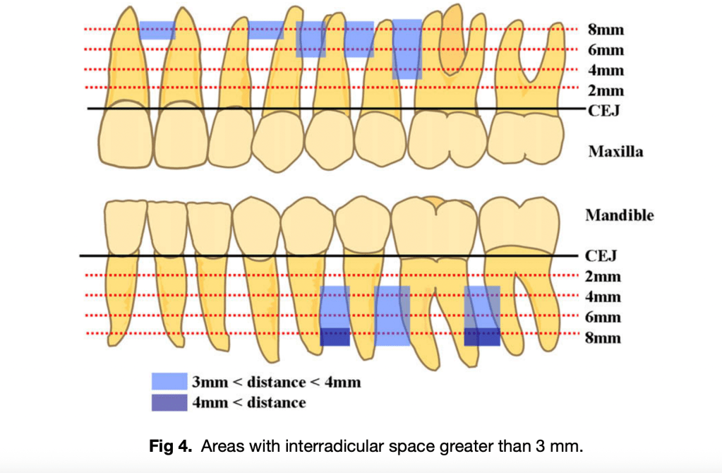
Interradicular space greater than 3 mm is mandatory for safe miniscrew placement. True
In the maxillary intermolar region, angulated miniscrew placement is recommended due to large safety depth but limited interroot space. True
In the mandibular incisor region, sufficient interradicular space (>3 mm) is available at 4 mm from CEJ. False
Buccal bone thickness is generally greater in posterior regions compared to anterior regions. True
Panoramic radiographs are equally reliable as CT for identifying miniscrew safe zones. False
As orthodontic students, you’re entering the field at an exciting time of technological innovation. Traditional thermoformed aligners have revolutionized orthodontic treatment, but now we’re witnessing the emergence of direct 3D-printed aligners that promise to transform the way we approach clear aligner therapy.
Understanding Direct 3D-Printed Aligners
Direct 3D-printed aligners are fabricated using specialized photopolymer resins, with Tera Harz TC-85 being the most prominent FDA-approved material. Unlike traditional aligners that are vacuum-formed over printed models, these aligners are printed directly as complete shells, offering unprecedented design flexibility and customization possibilities.
Revolutionary Design Capabilities
What sets direct 3D-printed aligners apart is their unlimited design possibilities. As future orthodontists, you’ll have the ability to:
Fine-tune biomechanics by adjusting the thickness at any part of the aligner, enabling precise force delivery and production of countermoments for root movement. This level of customization was previously impossible with conventional thermoformed aligners.
Incorporate specialized features such as:
Cutouts and bite ramps for specific clinical situations
Class II advancement wings similar to functional appliances
Integrated tubes for TMA spring insertion in cases requiring gap closure after relapse
Hooks for elastics built directly into the aligner design
Pressure columns for extrusion movements, eliminating the need for attachments
Customized trim lines for optimal retention and comfort
Material Properties and Clinical Advantages
Shape Memory Technology
The most remarkable feature of TC-85 resin is its shape memory capability. After exposure to high temperatures, aligners can be deformed to easily snap over undercuts, but when maintained in the oral environment (above 30°C) for the prescribed 22 hours daily, any deformation self-corrects. This property ensures consistent force delivery throughout the treatment period.
Force Delivery Characteristics
Research demonstrates that direct 3D-printed aligners apply continuous, light forces due to their unique viscoelastic properties. Studies show that force levels during extrusion movements are significantly lower compared to thermoformed aligners, potentially reducing patient discomfort and unwanted side effects.
The ability to customize thickness at different aligner regions allows for better force distribution, optimizing tooth movement while minimizing adverse effects. This represents a significant advancement in biomechanical control that you’ll appreciate in your clinical practice.
Durability and Performance
TC-85 aligners maintain their mechanical properties for at least one week of intraoral use. Unlike thermoplastic aligners, they can remain at body temperature without losing force from deformation, ensuring consistent treatment progression. However, surface roughness and porosity increase after one week of wear, similar to conventional aligners.
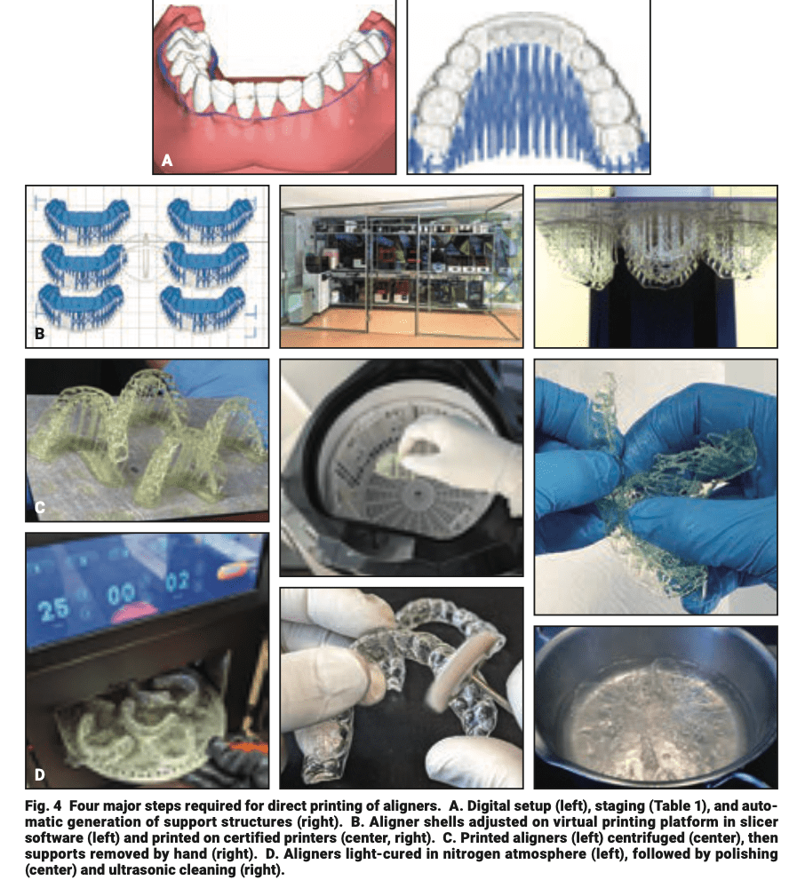
Workflow Steps
Digital Setup & Staging – Software platforms (e.g., Graphy DAD) – Movement limits: 0.25–0.30 mm per tooth; ≤2° angulation
3D Printing – 6–8 aligners per run (30–60 min)
Cleaning & Support Removal – Centrifuge 6 min; manual support removal
Post-Processing – UV cure (17–25 min in N₂); polish; ultrasonic clean
Software Tools
Graphy Direct Aligner Designer (free)
Commercial: 3Shape, Blue Sky Plan, NemoStudio
📌 Source: Ludwig B, Ojima K, Schmid JQ, Knode V, Nanda R. Direct-Printed Aligners: A Clinical Status Report. J Clin Orthod. 2024;58(11):658–668
Sex Difference: Girls reach each stage earlier than boys
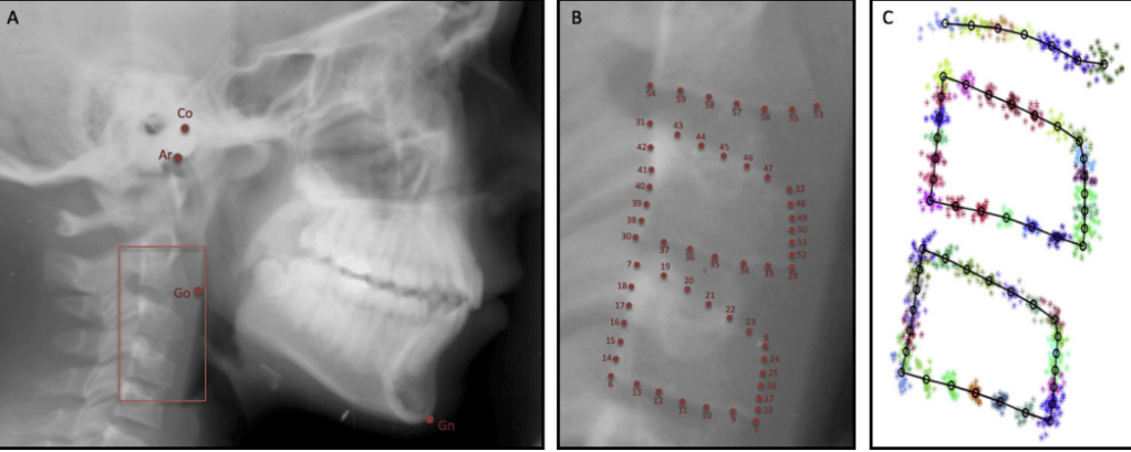
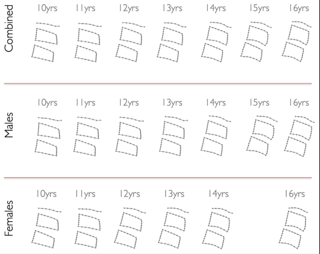
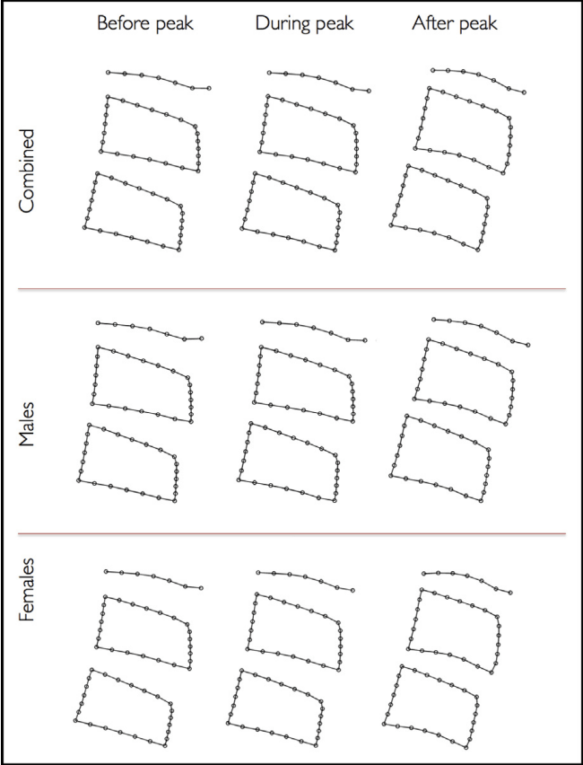
Study Findings (Gray et al., 2016)
✅ Morphometric changes match classic CVM descriptions ❌ CVM stages did not reliably predict mandibular growth peak 👉 Growth peak often occurred before or after CS3, not always between CS3–CS4
Peak mandibular growth: typically occurs around CS3, but study shows high variability:
32% after CS3
28% after CS1
20% after CS2
20% after CS4
No growth peak at CS5 or CS6
Clinical Pearls
CVM can confirm if peak growth has passed, but
Chronologic age is often a better predictor than CVM alone
A 12-year-old boy presents for orthodontic evaluation. His lateral cephalogram shows concavity in the inferior borders of C2 and C3, but not yet in C4. The vertebral bodies are less trapezoid, approaching rectangular. What can be inferred about his mandibular growth peak?
A. Growth peak is most likely already passed B. Growth peak is occurring now or will occur soon C. Growth peak cannot occur at this stage D. Growth peak will only occur at CS5–CS6
Answer: B Explanation: Concavities at C2 and C3 correspond to CS3, which is often associated with the timing of peak mandibular growth. However, variability exists (some peak after CS1, CS2, or CS4).
Q2.
During a growth assessment, a girl’s cephalogram shows all three cervical vertebrae (C2–C4) with distinct concavities, and the vertebral bodies appear rectangular and taller. She is 14 years old. What is the most likely clinical implication?
A. She is approaching mandibular growth peak B. She is currently at growth peak C. She has already passed mandibular growth peak D. She will have another growth spurt at CS6
Answer: C Explanation: Distinct concavities and rectangular vertebrae (CS4 or later) suggest the growth peak has passed.
Q3.
Which of the following statements best reflects the findings of the study?
A. CVM staging alone is a reliable predictor of mandibular growth peak B. Morphometric analysis can clearly differentiate “before” and “during” mandibular growth peak C. Chronologic age is a better predictor of mandibular growth peak than CVM stage D. Mandibular growth always occurs after CS3
Answer: C Explanation: The study found chronologic age correlated more consistently with mandibular growth than CVM staging. Morphometric differences were only clear after the peak, not before vs during.
Q4.
An orthodontist uses CVM staging to plan functional appliance therapy in a boy. His CVM stage is CS3. According to the study, what percentage of children actually reach peak mandibular growth after CS3?
A. 20% B. 28% C. 32% D. 50%
Answer: C Explanation: Only 32% of participants reached peak mandibular growth after CS3, highlighting variability.
Q5.
Which of the following sex differences were observed in the study regarding mandibular growth peak timing?
A. Boys reached peak earlier (mean 11.7 yrs) than girls (mean 12.8 yrs) B. Girls reached peak earlier (mean 11.7 yrs) than boys (mean 12.8 yrs) C. No sex differences were found in timing of growth peak D. CVM stage timing was identical in both sexes
Answer: B Explanation: Girls reached mandibular growth peak earlier (mean 11.7 years) than boys (12.8 years).
Micro‑implant‑supported maxillary skeletal expansion (MSE) applies orthopedic forces through palatal mini-implants to split the midpalatal suture, yet its soft‑tissue effects have been less clear than its skeletal outcomes
This study used 3D stereophotogrammetry to quantify facial soft‑tissue changes immediately after expansion and at one‑year retention, revealing significant, stable changes localized to the paranasal region, upper lip, and both cheeks.
🔹 Protocol
Appliance: MSE with 4 palatal mini-implants
Activation: 0.25 mm turns, 1–2/day (per Cantarella protocol)
Monitoring: Midline diastema + CBCT confirmation
🔹 Soft Tissue Effects (3D Analysis)
Paranasal area → mean displacement 1.3–1.5 mm
Cheeks → greater displacement (R: 2.4 mm, L: 2.9 mm)
Direction: forward + lateral (dominant anterior)
Stable at 1-year retention
🔹 Clinical Pearls
✅ Changes most visible around cheeks and paranasal areas ✅ Facial symmetry can vary → expansion often slightly asymmetric ✅ 3D scans are superior to 2D photos for monitoring changes ✅ No significant relapse after 1 year
🔹 Quick Comparison
Expander
Effect
Notes
Tooth-borne (Hyrax/Haas)
Dentoalveolar tipping
Risk of root resorption
Bone-borne (MSE)
True skeletal expansion
Stable soft tissue changes
Bottom line
MSE produces significant, forward‑lateral soft‑tissue enhancement centered on the paranasal/upper lip and cheeks, with the cheeks showing the largest and most clinically perceptible displacements that remain stable at one year