Rabie et al., Angle Orthodontist, 2003;73:457–465
Rabie et al., Angle Orthodontist, 2003;73:457–465
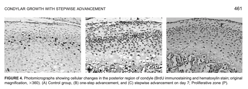
Stepwise mandibular advancement → Mechanical strain → ↑ Replicating mesenchymal cells → ↑ Osteoprogenitor population → ↑ Bone formation → ↑ Condylar growth potential
| Parameter | Details |
|---|---|
| Animal | 250 female Sprague-Dawley rats |
| Age | 35 days |
| Control | Natural growth |
| One-step (OS) | 3.5 mm advancement + 3 mm inferior displacement |
| Stepwise (SW) | 2 mm initial advancement → +1.5 mm on Day 30 |
| Cell marker | BrdU immunostaining |
| Assessment | Replicating mesenchymal cells + new bone formation |
| Regions studied | Anterior, middle & posterior condyle |
| Main site of response | Posterior condyle |
Forward mandibular positioning
↓
Stretching of posterior condylar tissues
↓
Mechanical strain
↓
↑ Mesenchymal cell replication
↓
Mesenchymal cells → chondroblasts / osteoblasts
↓
Cartilage formation + vascular invasion
↓
Endochondral ossification
↓
First advancement: 2 mm
Second advancement: +1.5 mm on Day 30
Cell proliferation precedes bone formation.
| Feature | One-Step | Stepwise |
|---|---|---|
| Advancement | 3.5 mm at once | 2 mm → +1.5 mm |
| Initial cellular response | Greater | Lower |
| Cell replication | Early increase → declines | Repeated increase after each advancement |
| Bone formation | Early peak → declines | Sustained/repeated increase |
| Long-term effect | Returns toward natural growth | Greater bone formation |
| Day 60 bone formation | Similar to natural growth | 49% higher |
First advancement
→ recruits mesenchymal cells
→ cells proliferate
→ differentiate
→ bone formation
Second advancement
→ provides new mechanical stimulus
→ recruits another population of replicating cells
→ increases osteoprogenitor pool
→ additional bone formation
“Advance → Recruit → Differentiate → Form bone → Advance again → Recruit again.”
Rabie et al. demonstrated that stepwise mandibular advancement produces repeated mechanical strain, increasing mesenchymal cell replication in the posterior condyle; this expands the osteoprogenitor cell population and subsequently enhances endochondral bone formation and condylar growth potential.
| # | Question | Answer |
| 1 | Define friction in orthodontics | Force opposing relative motion between two systems (bracket, archwire, ligation) that are in contact |
| 2 | Why is friction inevitable in orthodontics? | Because the bracket, archwire, and ligation are always in physical contact during sliding mechanics |
| 3 | Name the two types of friction | Static friction and kinetic friction |
| 4 | Define static friction | Friction that opposes an applied force; its magnitude equals whatever is needed to prevent motion until overcome. |
| 5 | Define kinetic friction | Friction that opposes the direction of motion once movement has started; usually less than static friction. |
| 6 | Which type of friction is clinically more relevant in orthodontics, and why? | Static friction, because continuous sliding motion along the archwire rarely occurs clinically. |
| 7 | Why is kinetic friction considered practically irrelevant in tooth movement? | Because orthodontic tooth movement is not continuous sliding but an intermittent, quasi-static process. |
| 8 | What is meant by “quasi-static thermodynamic process” in sliding mechanics? | A slow process that passes through a sequence of states close to equilibrium, rather than true continuous motion. |
| 9 | Who authored the classic critical review on friction and resistance to sliding? | S. Jack Burrow, published in AJO-DO 2009. |
| 10 | What does resistance to sliding (RS) mean? | The total resistance encountered by a wire sliding through a bracket comprises friction, binding, and notching. |
| # | Question | Answer |
| 11 | In sliding mechanics, where are forces applied relative to the center of resistance (Cres)? | Away from the center of resistance of the segments being moved |
| 12 | What is the consequence of applying force away from Cres? | It generates moments that tip the segments in different planes |
| 13 | Describe the sagittal-plane effect of retraction force in extraction cases | Anterior segment tips distally, posterior segment tips mesially |
| 14 | Describe the transverse-plane effect | Mesial out-rotation of canines and mesial in-rotation of premolars |
| 15 | Describe the vertical-plane effect | Deepening of the bite |
| 16 | How does frictionless mechanics counter these unwanted moments? | Alpha and beta moments incorporated into loops compensate for the moments generated by the applied force |
| 17 | How does sliding mechanics generate the necessary counteracting moments? | Through the interaction between bracket and wire (contact and binding), not through loop bends |
| 18 | What is expressed as a result of bracket-wire interaction in sliding mechanics? | First, second, and third order movements (tip, torque, in-out) |
| 19 | Why is understanding sliding biomechanics a prerequisite to understanding friction’s role? | Because friction’s clinical significance depends on how forces and moments are generated during sliding |
| 20 | What produces the tipping, torqueing, and in-out corrections in sliding mechanics if not loop bends? | Interactive contact/binding between archwire, bracket, and ligation |
| # | Question | Answer |
| 21 | Is friction entirely undesirable in orthodontics? | No; friction is both a hindrance during sliding and a necessity for generating corrective couples |
| 22 | What is desired during retraction with sliding mechanics? | Reduced friction so the wire can freely slide through the bracket |
| 23 | What stops further tipping of a tooth during retraction? | Contact of the bracket with the wire, which prevents further tipping |
| 24 | What creates the moment of the couple during retraction? | Classic frictional contact between bracket and wire plus the wire’s resilience |
| 25 | What moment is induced in the anterior segment during retraction? | Distal root uprighting moment |
| 26 | What moment is induced in the posterior segment during retraction? | Mesial (root) uprighting moment |
| 27 | What happens after the uprighting movement occurs? | The frictional contact between bracket and wire is relieved |
| 28 | What happens to the tooth once contact is relieved? | It is free to tip again for the next cycle |
| 29 | What is this repeating cycle called? | Stick-slip phenomenon, also called “walking of the canine” |
| 30 | Is stick-slip specific to canine retraction only? | No; a similar contact-based couple is created for torqueing and in-out movements as well |
| 31 | Summarize the ideal friction requirement in sliding mechanics | Low friction is needed for sliding, but adequate frictional contact is needed to deliver couples |
| 32 | What are the two opposing frictional requirements in sliding mechanics called (concept)? | The friction paradox — lower friction desired for translation, higher friction/binding desired for couple generation |
| # | Question | Answer |
| 33 | Why is force decay necessary in regular sliding mechanics? | For the couple from bracket-wire interaction to be adequately expressed for tip, torque, and in-out correction |
| 34 | What happens if the applied force does not decay or is too high? | The couple generated will be inadequate for tipping, torqueing, and in-out movements to occur |
| 35 | Which reference discusses force decay in incisor retraction with mini-implant anchorage? | Upadhyay, Yadav, and Nanda, Journal of Orthodontics 2014 |
| 36 | How does high sustained force affect binding-generated couples? | It prevents adequate binding-based couple generation needed for correction movements |
| # | Question | Answer |
| 37 | Name three clinical scenarios where sliding mechanics is typically used | Generalized spacing cases, premolar extraction cases, enmasse distalization with implants |
| 38 | Does implant-assisted space closure fall under friction or frictionless mechanics? | Friction mechanics, since it involves the archwire sliding through brackets |
| 39 | What is the major biomechanical difference between conventional and implant-assisted sliding? | Difference in space utilization and line of force |
| 40 | How much anchorage loss occurs with implant-assisted sliding? | Almost none — anchorage conservation is nearly full |
| 41 | Which types of space closure can be achieved with implant-supported sliding? | Group A or Group C space closure |
| 42 | Why is the line of force diagonal in implant-assisted sliding? | Because implants are usually placed higher than the molar hooks |
| 43 | How does implant placement affect the line of force relative to Cres? | It brings the line of force closer to the center of resistance |
| 44 | What effect does this closer line of force have on the moments generated? | Moments are of lesser magnitude compared with conventional mechanics |
| 45 | What effect does lower moment magnitude have on the required couple? | The moment of the couple required also becomes lesser |
| 46 | Can the line of force be modified in implant mechanics? | Yes, infinitely, based on implant and hook position relative to the case requirement |
| # | Question | Answer |
| 47 | Who developed V-bend sliding mechanics and when? | Thomas F. Mulligan, in the 1970s |
| 48 | What is the primary clinical application of V-bend mechanics? | Closing space by moving individual teeth (canine retraction or molar protraction) |
| 49 | What key concept did Mulligan introduce? | Differential moment as a means of effective intraoral anchorage |
| 50 | How is differential moment achieved? | By applying unequal alpha and beta moments |
| 51 | How are moments and forces applied separately in V-bend mechanics? | Moments via the continuous archwire and its bends; force via auxiliaries like elastomeric chain or closed-coil springs |
| 52 | Why is an off-center V-bend used? | To create unequal moments, with a higher moment applied to the anchorage teeth |
| 53 | How does bend position affect wire segment length and moment? | Bend closer to a bracket shortens that wire segment; shorter wires have higher bending moments than longer wires |
| 54 | Which bracket experiences the higher moment: closer or farther from the V-bend? | The bracket closer to the V-bend |
| 55 | How does a higher moment affect tipping of that segment? | The segment with higher moment undergoes less tipping for the same reciprocal force, establishing differential anchorage |
| 56 | What V-bend angle is used for 0.016″ round stainless steel wire? | 45° |
| 57 | What V-bend angle is used for 0.018″ wire? | 30° |
| 58 | What V-bend angle is used for 0.020″ wire? | 15° |
| 59 | What is the relationship between wire size and V-bend angle? | Inverse relationship — thinner wire needs a larger V-bend angle |
| 60 | Who published the force system analysis of V-bend sliding mechanics? | Siatkowski RE, JCO 1994 |
| # | Question | Answer |
| 61 | State the first law of friction | Frictional force is proportional to the normal applied load by a constant, the coefficient of friction |
| 62 | State the second law of friction | The coefficient of friction is independent of apparent contact area |
| 63 | State the third law of friction | The coefficient of friction of a couple is independent of the sliding velocity |
| 64 | According to the second law, should bracket/wire dimensions matter clinically? | Theoretically no, but clinically dimensions matter with respect to the critical contact angle |
| 65 | Why does dimension still matter despite the second law? | Because dimensions determine the critical contact angle, beyond which binding/notching (not classical friction) dominates |
| # | Question | Answer |
| 66 | Who proposed dividing resistance to sliding into three components? | Kusy and Whitley . |
| 67 | Name the three components of resistance to sliding | Friction (FR), binding (BI), notching (NO) . |
| 68 | Define friction (FR) component | Static or kinetic friction due to wire contact with flat bracket surfaces . |
| 69 | Define binding (BI) component | Contact between wire and the corners of the bracket, occurring when the tooth tips or wire flexes . |
| 70 | When does binding occur clinically? | When a force applied to move a tooth causes it to tip until the wire contacts the bracket corners . |
| 71 | Define notching (NO) component | Permanent deformation of the wire at the wire-bracket corner interface . |
| 72 | Is notching reversible? | No, it represents permanent wire deformation . |
| 73 | What is the sequence of resistance components as contact angle increases? | Friction → Binding → Notching |
| # | Question | Answer |
| 74 | Define the contact angle (θ) | The angle between the archwire and the bracket slot |
| 75 | Define the critical contact angle (θc) | The angle boundary between classical frictional behavior and binding/notching phenomena . |
| 76 | What happens when θ ≤ θc? | Classical friction occurs |
| 77 | What happens when θ > θc? | Binding and notching begin, increasingly restricting sliding mechanics . |
| 78 | What is the theoretical maximum θc for nominal bracket/wire dimensions? | Approximately 3.7 degrees for standard slot sizes . |
| 79 | What range does θc typically fall within? | Between 0 and approximately 4 degrees . |
| 80 | Who established the mathematical derivation for θc? | Kusy and Whitley (EJO 1999) . |
| 81 | Why is knowledge of both wire AND bracket dimensions necessary to calculate θc? | Knowledge of the archwire-bracket combination is needed, not either component alone . |
| 82 | What clinical strategy minimizes binding and notching? | Selecting archwire and slot size combinations that keep the contact angle low |
| 83 | Should sliding mechanics ideally begin when θ is much less than θc, equal to θc, or greater? | Sliding should be initiated when θ approximates θc, avoiding over-alignment before sliding and avoiding exceeding θc . |
| # | Question | Answer |
| 95 | Why would an orthodontist prefer stainless steel wires for sliding mechanics? | Lowest surface roughness and coefficient of friction, giving more efficient force delivery |
| 96 | Why might beta-titanium be avoided during heavy sliding mechanics despite good elasticity? | Higher friction and greater variability in frictional forces reduce efficiency of force delivery |
| 97 | How does implant-assisted sliding reduce the friction-related side effects of conventional sliding? | By reducing moment magnitude near Cres, it reduces the binding-generated moments and associated tipping |
| 98 | Compare frictionless and friction (sliding) mechanics in generating couples | Frictionless mechanics use built-in loop moments (alpha/beta); sliding mechanics rely on bracket-wire binding/friction contact |
| 99 | What is a clinical implication of understanding the critical contact angle? | It can help avoid unnecessary over-alignment before sliding and prevent excessive binding, potentially reducing treatment time . |
| 100 | Summarize the key biomechanical principle for effective sliding mechanics | Balance low sliding friction (for translation) with adequate binding contact (for necessary couple generation) while selecting materials/dimensions to control the coefficient of friction and critical contact angle |
The angulation of the Twin Block appliance’s inclined planes underwent three distinct stages of development, each driven by clinical observations and biomechanical reasoning.
The earliest Twin Block appliances, developed by W.J. Clark, featured bite blocks angulated at 90° to the occlusal plane. Patients were required to consciously posture the mandible forward to occlude the blocks. However, many patients struggled to maintain this forward position and habitually returned to their original distal occlusal position, causing the flat-surfaced blocks to stack on top of each other. This resulted in a significant posterior open bite, a complication seen in approximately 30% of early Twin Block cases.
To resolve the compliance problem, the angulation was modified to 45° to the occlusal plane. This immediately guided the mandible forward more passively, eliminating the stacking issue. A 45° angle provides an equal downward and forward force component to the lower dentition, promoting both vertical and sagittal growth stimuli. Clark continued using this angulation clinically for approximately 8 years before the next modification.
After the prolonged use of the 45° design, the angulation was increased to 70° to the occlusal plane — the current standard configuration. This steeper angle introduces a more horizontal force component, theoretically encouraging greater forward (sagittal) mandibular growth rather than a combined downward-forward stimulus. The 70° angle is now incorporated into the standard Twin Block design with maxillary and mandibular acrylic base plates.
| Angulation | Rationale | Limitation |
|---|
| Angulation | Rationale | Limitation |
|---|---|---|
| 90° | Original design; edge-to-edge block contact | ~30% posterior open bite; poor compliance |
| 45° | Equal forward + downward force vector | Used for 8 years; less horizontal growth stimulus |
| 70° | More horizontal force; greater forward mandibular growth | May reduce mandibular postural guidance |
Clinically, if a patient struggles to maintain the forward mandibular posture with a 70° design, it is advisable to revert to a 45° angulation to facilitate easier maintenance of the protruded position.
 Dentowesome