(Based on Linder-Aronson et al., Am J Orthod, 1986)
As orthodontists, we often label a child as a “vertical grower” or “long-face case” very early—and then plan mechanics accordingly.
But what if that growth direction is not fixed?
What if airway obstruction and breathing mode are quietly influencing mandibular posture and growth direction—and correcting the airway changes the skeletal trajectory?
Understanding Mandibular Growth Direction (MGD)
What do we mean by “mandibular growth direction”?
- Mandibular growth direction refers to the direction in which the chin (gnathion) moves during growth
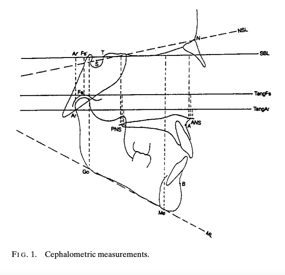
- It is assessed by:
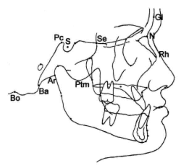
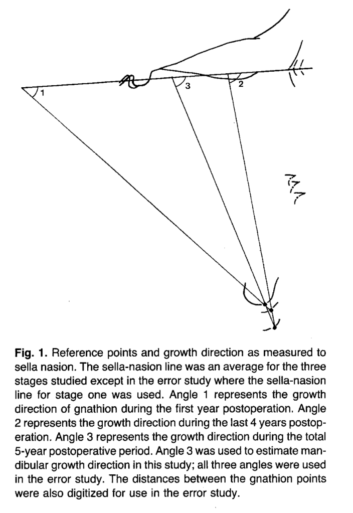
- Superimposing serial cephalograms on stable cranial base structures
- Tracking the movement of gnathion
- Measuring its angle relative to the Sella–Nasion (SN) plane
Simplified interpretation:
- More horizontal MGD → forward chin growth → better profile, less vertical facial height
- More vertical MGD → downward/backward chin growth → long face tendency
📌 MGD represents the sum total of multiple growth influences, not just mandibular length.
Question to Ponder
If two children have the same mandibular length, can they still have very different facial profiles? Why?
2. Why Airway Obstruction Matters in Facial Growth
What happens in children with enlarged adenoids?
Children with severe nasopharyngeal obstruction often show:
- Mouth breathing
- Lowered mandibular posture
- Increased lower anterior face height
- Steeper mandibular plane
- Retrognathic mandible
These features are classically associated with vertical growth patterns.
Cause → Mechanism → Effect
| Step | Explanation |
|---|---|
| Cause | Enlarged adenoids → nasal obstruction |
| Mechanism | Mouth breathing → mandible held in a lowered position |
| Effect | Increased lower face height + vertical mandibular growth |
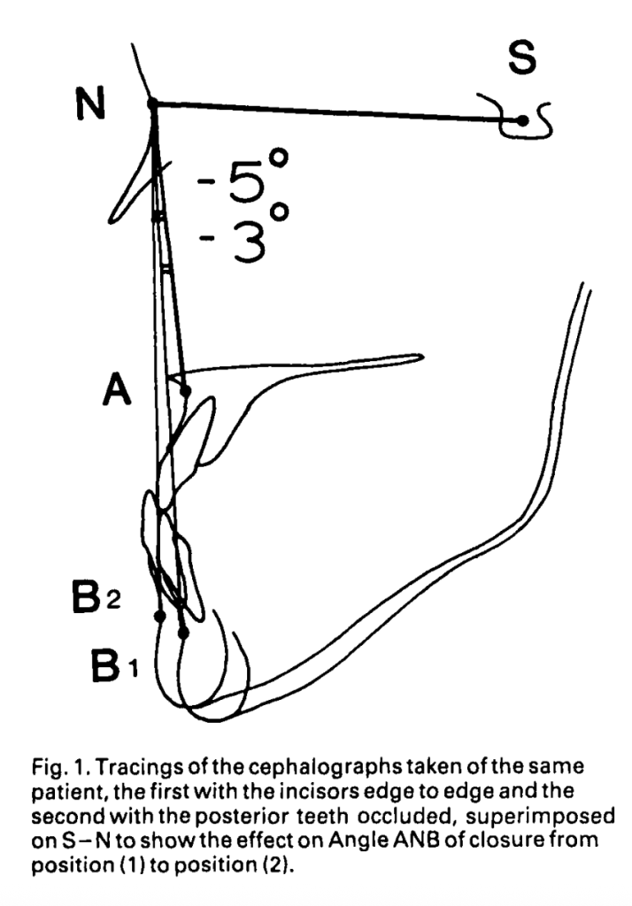
⚠️ The key point is mandibular posture, not just airflow.
Question to Ponder
Is it the path of air or the position of the mandible during breathing that matters more for growth?
3. What Is Adenoidectomy Expected to Do (The Hypothesis)
The authors asked a simple but powerful question:
If nasal breathing is restored after adenoidectomy, does mandibular growth direction change?
Null Hypothesis: Restoring nasal breathing does not affect mandibular growth direction.
If the mandible becomes:
- More horizontal → hypothesis rejected
- Same as controls → hypothesis rejected
4. How the Study Was Designed
Study Groups
| Group | Description |
|---|---|
| Adenoidectomy group | 38 children (7–12 yrs) with severe nasal obstruction who changed from mouth to nasal breathing |
| Control group | 37 age- and sex-matched children with clear airways |
Important Controls:
- No orthodontic treatment in either group
- 5-year follow-up using serial cephalograms
- Separate analysis for boys and girls
Why not short-term?
- Small growth increments exaggerate measurement errors
- Reliable conclusions require ≥10 mm of chin growth
📌 Important learning point:
MGD measurements are highly sensitive to superimposition errors—long-term data matters.
5. What Did the Study Find? (Core Results)
A. Girls After Adenoidectomy
- Showed significantly more horizontal mandibular growth
- More horizontal than even female controls
- Suggests partial recovery from earlier vertical growth
B. Boys After Adenoidectomy
- Trend toward more horizontal growth
- But not statistically significant
- Still showed large individual variation
| Group | Change in MGD After Adenoidectomy |
|---|---|
| Girls | Significant horizontal shift |
| Boys | Horizontal trend, not significant |
| Both | Greater variability than controls |
| Group | Boys MGD Mean (SD) | Girls MGD Mean (SD) | Variability vs Controls |
|---|---|---|---|
| Adenoidectomy | 58° (18°) | 61° (16°) | Higher (P<0.05) |
| Controls | 62° (11°) | 72° (9°) | Lower |
Question to Ponder
Why might girls show a clearer skeletal response than boys after airway correction?
6. Why Was Growth More Variable After Adenoidectomy?
Animal studies help explain this.
Key Insight from Primate Studies:
- Some subjects respond to obstruction by:
- Holding mandible down → vertical growth
- Others:
- Open mouth briefly for each breath → normal growth
👉 Different neuromuscular adaptations → different growth outcomes
CLINICAL IMPLICATIONS
1️⃣ Growth Direction Is Not Always Fixed
- Traditionally, vertical growers were treated by adapting mechanics
- This study suggests growth direction can partially recover naturally
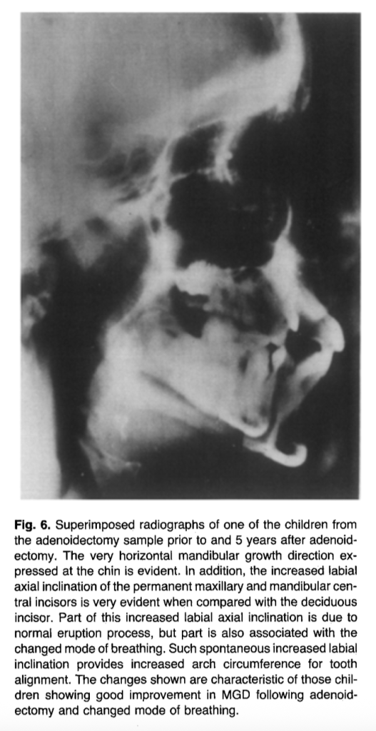
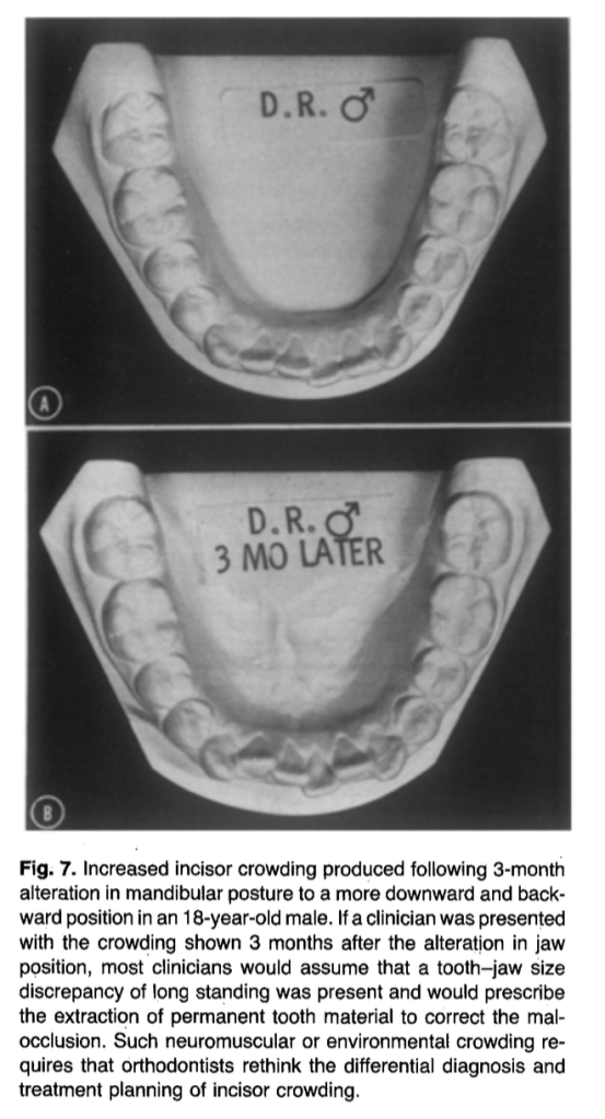
2️⃣ Incisor Crowding May Be Environmental
After adenoidectomy:
- Incisors often change from retroclined → proclined
- Arch circumference may increase
- Some crowding may resolve without extractions
📌 Not all crowding = tooth–jaw size discrepancy
3️⃣ Timing Matters
- Adenoids are largest around 5 years
- Often regress naturally later by age 10 years
- Surgery should be reserved for symptomatic young children
4️⃣ Airflow Alone Is Not Enough
- Increased nasal airflow ≠ changed mandibular posture
- Posture is the biological driver of growth change
Question to Ponder
How might early airway evaluation change your extraction vs non-extraction decisions?
Final Take-Home Message
The mandible does not grow in isolation.
It grows within a functional environment—especially the airway.
As orthodontists, ignoring that environment means missing half the diagnosis.