Palatal miniscrews provide reliable intraoral anchorage for distalization and expansion while minimizing compliance issues and anchorage loss, making them foundational in modern biomechanics.
🩺 Clinical Objective
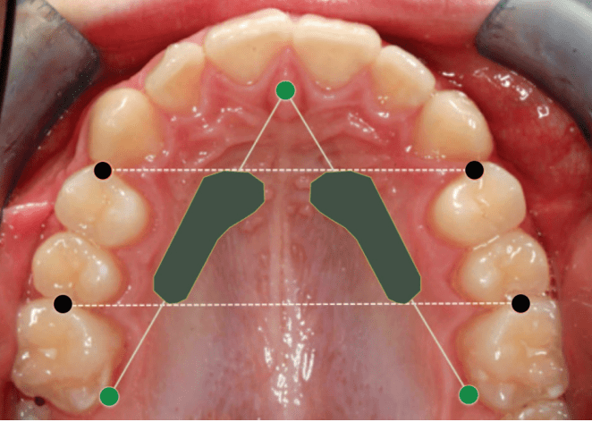
Identify safe and reliable sites for orthodontic mini-implant (OMI) insertion in the paramedian anterior palate based on vertical bone height (VBH) and anatomical safety.
📍 Optimal Insertion Zone
| Reference Point | Safe Zone Coordinates | Average VBH (mm) | Remarks |
|---|---|---|---|
| From incisive foramen | 3–4 mm posterior | 7–11 mm | Consistent adequate bone height |
| From midpalatal suture | 3–9 mm lateral | ≥5 mm (safe minimum) | Ideal for OMI placement |
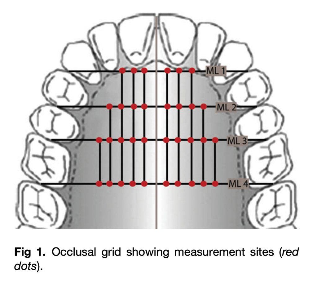
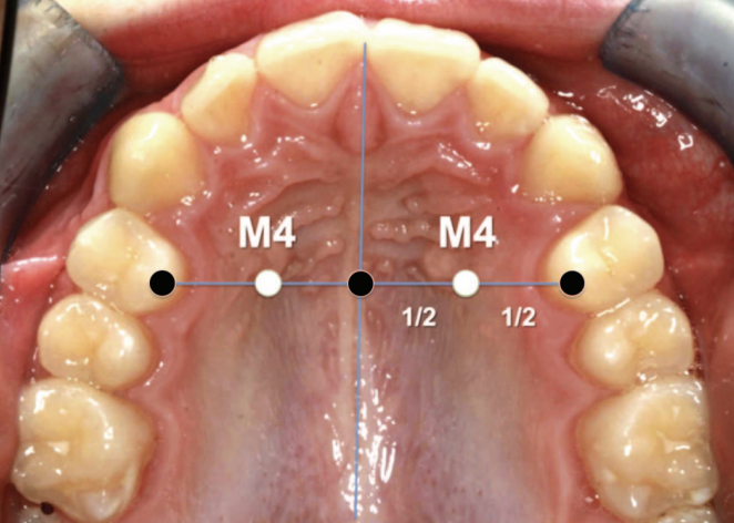
| M4 Site (Winsauer et al., 2011) | 3 mm AP, 6 mm ML | 10–11 mm | Preferred site for molar distalizers |
| Posterior to 12 mm | 9–12 mm lateral | 4–5 mm | Diminishing VBH; use with caution |
Note: “M4 site” — halfway from midpalatal suture to the first premolar along the line through the palatal cusp of the first premolar
🧭 Insertion Guidelines
- Implant size: 2.0 mm diameter, 10–14 mm length
- Minimum VBH required: ≥ 5 mm
- Insertion direction: Perpendicular to palatal surface
- Pre-check: Lateral ceph or CBCT (especially in thin palates)
- Avoid: Midpalatal suture in growing patients (growth disturbance risk)
🧫 Mucosal Considerations (Marquezan et al., 2012)
- Palatal mucosa is thickest anterolaterally; estimate with an LA needle and stop (rubber disc) to plan trans-mucosal length and ensure adequate intraosseous purchase.
- Engaging both cortical plates (where feasible) decreases trabecular stress and enhances primary stability, but even single-cortex engagement with adequate VBH supports orthodontic load ranges.
| Site (AP × ML) | Mucosal Thickness (mm) |
|---|---|
| 4 × 6 mm | 5.26 |
| 8 × 6 mm | 4.39 |
| 4 × 3 mm | 3.37 |
| 8 × 3 mm | 2.71 |
Thicker keratinized mucosa at paramedian regions reduces infection and inflammation risk.
⚠️ Anatomical & Safety Notes
- Safe region: AP 3–9 mm, ML 3–9 mm (anterior paramedian zone)
- Arteria palatina: Rarely encountered and thin
- Risk of nasal perforation: Minimal if CBCT verified
- Preferred for:
- Molar distalizers
- Hybrid expanders (e.g., Hyrax)
- Absolute anchorage appliances
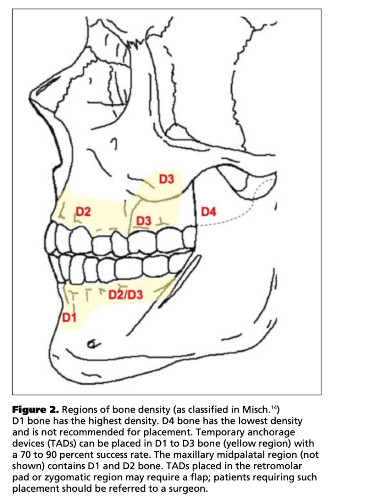
📊 Bone Density Summary
| Location | Bone Density | Clinical Relevance |
|---|---|---|
| 3 mm lateral to suture | > 50–70 % hard tissue fraction | High stability potential |
| Posterior regions | Decreasing density | Use caution |
🦷 Clinical Scenario–Based MCQs
Q1. Site Selection & Risk Avoidance
A 17-year-old female requires anchorage for bilateral molar distalization. You plan mini-implant placement in the anterior palate. Which insertion site minimizes risk of nasopalatine canal injury while ensuring adequate vertical bone height (VBH)?
A. 1 mm posterior to incisive foramen, 2 mm lateral to midpalatal suture
B. 3–4 mm posterior to incisive foramen, 3–9 mm lateral to suture
C. 8–10 mm posterior to incisive foramen, 12 mm lateral to suture
D. Midpalatal suture at canine level
Answer: ✅ B.
Explanation: The safe paramedian zone (AP 3–4 mm, ML 3–9 mm) provides ≥ 5 mm VBH and avoids the incisive foramen.
Q2. Growth Consideration
In a 12-year-old patient, you consider midpalatal placement of mini-implants. Which is the primary concern?
A. Thin cortical bone
B. High mucosal thickness
C. Risk of interfering with midpalatal suture growth
D. Perforation into nasal floor
Answer: ✅ C.
Explanation: The midpalatal suture may ossify variably up to late adolescence; premature insertion can disturb transverse growth (Asscherickx et al., 2005).
Q3. Imaging Decision
Routine lateral cephalogram shows limited palatal height near the first premolar line. What is the most appropriate next diagnostic step before insertion?
A. Proceed using standard depth screw
B. Use intraoral periapical radiograph
C. Request CBCT for precise VBH assessment
D. Probe mucosa to estimate bone depth
Answer: ✅ C.
Explanation: CBCT provides accurate 3D VBH estimation and should be used when cephalogram suggests borderline bone height.
Q4. Implant Stability
A clinician inserts a 2 mm diameter, 10 mm length screw into an area with 4 mm VBH. What is the likely clinical outcome?
A. Adequate anchorage
B. Reduced initial stability and possible failure
C. Excessive soft-tissue coverage
D. Root contact with lateral incisor
Answer: ✅ B.
Explanation: Minimum 5 mm bony support is essential for stability against 0.5–3 N orthodontic forces; < 5 mm risks loosening.
Q5. Safe Depth Estimation
During anesthesia, the clinician probes mucosal thickness using the injection needle and finds 4.5 mm. If the CBCT indicates VBH of 8 mm at that site, what is the safe insertion length?
A. 8 mm
B. 10 mm
C. 12 mm
D. 14 mm
Answer: ✅ B.
Explanation: Total tissue = mucosa + bone ≈ 12.5 mm; a 10 mm implant ensures bony engagement without nasal floor perforation.
Q6. Bone Quality vs. Quantity
A patient shows high VBH (10 mm) but low bone density in posterior palate. What is the best site for improved cortical engagement?
A. Posterior palate near first molars
B. Anterior paramedian palate (AP 3–6 mm, ML 3–6 mm)
C. Midpalatal suture
D. 12 mm lateral to suture
Answer: ✅ B.
Explanation: The anterior paramedian palate has thicker cortical bone and higher density, improving primary stability.
Q7. Variability and Imaging Rationale
Despite the review identifying an ideal zone, why is routine individual imaging still recommended?
A. Studies showed consistent VBH across all patients
B. VBH strongly correlates with age alone
C. Great inter-individual variability in palatal bone height exists
D. Cephalometry alone can reliably measure VBH
Answer: ✅ C.
Explanation: Substantial anatomical variability necessitates individualized imaging (CBCT) for safety and accuracy.
Q8. Surgical Risk Awareness
If a screw is inserted blindly to 8 mm depth at AP 9 mm / ML 9 mm in an adult, which complication is most likely?
A. Root perforation
B. Nasal cavity penetration
C. Sinus floor damage
D. Palatal artery laceration
Answer: ✅ B.
Explanation: Beyond AP 9 mm, VBH often falls below 5 mm; deep insertion risks nasal perforation.
Q9. Cortical Involvement
Why does engaging both cortical plates enhance implant stability compared to single-layer cortical anchorage?
A. Reduces trabecular compression stress
B. Promotes faster osseointegration
C. Reduces mucosal overgrowth
D. Prevents micro-motion entirely
Answer: ✅ A.
Explanation: Dual cortical anchorage distributes stress and enhances mechanical resistance under orthodontic load (Kim et al., 2006).
Q10. Clinical Application
For a TopJet molar distalizer, which insertion site is ideal according to Winsauer et al. (2012)?
A. 6 mm posterior to incisive foramen, 12 mm lateral to midline
B. 3 mm posterior and 6 mm lateral to midpalatal suture (M4 site)
C. Directly over midpalatal suture at premolar level
D. 10 mm posterior, 9 mm lateral to midline
Answer: ✅ B.
Explanation: The M4 site (AP 3 mm, ML 6 mm) lies within the area of maximal VBH, offering safe, stable anchorage for molar distalization.