If bones could talk, they’d probably say, “Hey, stop pulling me!” But in the world of distraction osteogenesis (DO), that’s exactly what we do—intentionally stretch bone tissue to create new growth. Think of it as the orthodontic equivalent of a yoga instructor telling your jaw to lengthen and breathe.
While orthognathic surgery has been the gold standard for skeletal corrections, DO has stepped in as the cool new kid, especially for cases that were once deemed untreatable. But is it really the superior method, or just a fancier way to move bones? Let’s break it down.
Since its first craniofacial application by McCarthy et al. in 1992, DO has come a long way from being an experimental idea to a widely used technique for maxillary and mandibular expansion. But, like any orthodontic superhero, it comes with its strengths, weaknesses, and a history of trial-and-error that reads like a medical thriller.
The Origins: From Soviet Leg Braces to Jawline Makeovers
DO owes its roots (pun intended) to Ilizarov’s principles—a Russian orthopedic surgeon who figured out that bone can be stretched and tricked into regenerating. What started as a method for limb lengthening soon found its way into orthodontics when McCarthy et al. used it to lengthen hypoplastic mandibles in children.
Once researchers saw potential in midface and maxillary distraction, it became a game-changer for patients with clefts and severe maxillary hypoplasia—especially when traditional orthognathic surgery wasn’t an ideal option.
With miniature distraction devices, rigid external distraction (RED) systems, and intraoral appliances, the orthodontic world saw an explosion (well, controlled expansion) of techniques:
🔹 Cohen et al. (1997) – Introduced maxillary distraction in young children.
🔹 Polley & Figueroa (1997) – Used the RED device to treat severe maxillary hypoplasia.
🔹 Molina et al. (1998) – Tried a mix of facial masks and intraoral appliances for mixed dentition cases.
So, Does It Work? The Numbers Speak!
Swennen et al. (2001) reviewed 16 studies spanning 33 years (1966-1999) and found that maxillary advancements ranged from 1 mm to 17 mm. Not bad for a non-surgical approach, right?
Well, not so fast—relapse was reported in 50.4% of cases. That’s like getting a six-pack after months of workouts only for it to disappear when you eat one slice of pizza.
Rachmiel et al. (2005) reported stable results in 12 cleft patients after two years, showing that maxillary length (Condylion to A point) held its ground. But Krimmel et al. (2005) later threw a wrench into that optimism, noting a decrease in SNA and ANB angles just one year after distraction.
Cheung & Chua (2006) conducted a meta-analysis of 26 studies (1966-2003) on 276 cleft patients, revealing:
📌 Most maxillary advancements were between 5-9 mm.
📌 External distractors (68.8%) were more common than internal distractors (2.17%) and facial masks (25.72%).
📌 Maxillary relapse? 5.56% within two years—but only one study provided actual numbers.
One thing is clear: distraction osteogenesis works, but long-term stability is still a mixed bag.

The Study: Six Patients, One Mission—Expand That Maxilla!
Meet our VIPs: six Chinese patients (3 boys, 3 girls, average age 10.5 years), all of whom had:
✔ Cleft lip and palate (two unilateral, four bilateral)
✔ Primary lip and palate repair in infancy
✔ Anteroposterior maxillary hypoplasia (aka, their upper jaw was slacking)
✔ Class III malocclusion with a negative overjet (translation: their lower teeth were winning a battle they shouldn’t even be fighting)
These kids weren’t just getting braces—they were about to experience controlled bone expansion, courtesy of the Rigid External Distraction (RED) device.
1️⃣ Pre-Orthodontic Preparation – Because even bone stretching needs a good warm-up.
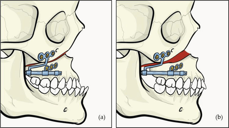
2️⃣ Complete High Le Fort I Osteotomy – A fancy way of saying, “Let’s surgically cut the upper jaw so we can move it.” where the maxilla was delicately detached with septal and pterygomaxillary disjunction. (Translation: we made it mobile but still attached—think of it as unlocking a door, not knocking it down.)
3️⃣ RED Device Installation – Think of this as the orthodontic version of a headgear, but instead of just pushing teeth, it’s stretching the entire upper jaw.
4️⃣ Latency Period (5 Days) – Let the jaw marinate before we start stretching it.
5️⃣ Active Distraction (1 mm/day) – The screws on the RED device were adjusted daily to pull the maxilla forward. (It’s like a gym for your bones—except you don’t have to do the work; your jaw does.)
6️⃣ Overcorrection Achieved! 🎉 – Because we know relapse is real, we stretched the maxilla a little extra to compensate for future setbacks.
7️⃣ Consolidation (6-8 Weeks) – The RED device stayed put to let the new bone solidify.
8️⃣ Device Removal & Orthodontics – After the expansion was done, the real party started: braces to fine-tune everything.

The study wasn’t just about making kids look less Class III—it was about proving that DO actually works (and hopefully, stays that way). Here’s how they did it:
📸 Lateral Cephalographs were taken at four key points:
🔹 T0 (Before Distraction) – “This is your jaw on cleft-induced hypoplasia.”
🔹 T1 (Immediately After Distraction) – “Congratulations, your maxilla has entered the chat.”
🔹 T2 (6 Months Later) – “Let’s see if your jaw likes its new position.”
🔹 T3 (1+ Year Later) – “Did it stay put, or did it sneak back?”
Instead of using simple before-and-after pictures (this isn’t a weight loss commercial), the researchers mapped out skeletal and dental landmark positions using a cranial base reference system.
How, you ask?
🔹 First, skeletal landmarks were pinpointed on the T0 cephalogram.
🔹 Then, these landmarks were transferred onto T1, T2, and T3 cephalograms using a best-fit method—aligning surrounding bone structures and trabecular patterns (Huang & Ross, 1982).
🔹 To keep things precise, an x-y coordinate system was created:
Y-axis: A perpendicular line intersecting the X-axis at sella
🔹 This coordinate system was then transferred onto each cephalogram for standardized measurements.
X-axis: Drawn 7° below the sella-nasion plane
Key Takeaways
✅ Overjet increased (yay, no more Class III woes!).
✅ Overbite decreased—except for our rebellious Case 5.
✅ Maxilla went forward (woo-hoo!) but then took a casual retreat backward over a year (boo!).
✅ Some vertical movement—first up, then down (the maxilla, not our enthusiasm).
✅ Teeth tagged along for the ride, moving anteriorly and inferiorly.
✅ Relapse? Oh yeah—about 9.6% at 6 months, increasing to 24.5% by a year.